Ben Okopnik
Jet Boat Lover
- Messages
- 58
- Reaction score
- 57
- Points
- 77
- Location
- Tampa FL
- Boat Make
- Other
- Year
- 1995
- Boat Model
- Other
- Boat Length
- Other
...then you're going to need a DVA (Direct Voltage Adapter) to do the peak-voltage measurements. You can buy one - they range from ~$35 to ~$200 on Amazon, depending on how much you want to get ripped off for and how long you're willing to wait - or, if you're at all handy, it's dead-easy, cheap, and quick to build one. I put mine together this morning in about 15 minutes out of the spare bits I had lying around, but if you don't have them, they should cost well under $10 from your local electronics shop.
Theory bits (feel free to skip):
A DVA is nothing more than a rectifier with a little smoothing circuitry following it; i.e., it turns very spiky, low duty-cycle AC (which is what your stator and trigger produce) into pulsating DC (which is what comes out of your switchbox), then flattens the pulses into a steady, measurable DC voltage by storing the peaks. The component values in it are fairly unimportant except for the voltage: since the "load" on the output is nothing but the meter you're using (typically 10MΩ or higher input impedance), and the storage capacitor is recharged more than 30 times per second (say, 300rpm/8 cylinders), the current is going to be in the microamp range and the capacitor value can be anything around 1µF (higher is better; the value determines how much you'll lose off the actual peak, and 1µF loses less than 1 volt in 400 at 30Hz.) The discharge resistor value just needs to be high (1MΩ or more) and the wattage is likewise unimportant due to the low current.
Last - just to help broaden the component choices (or to add to the confusion ), you can choose between a half-wave or a full-wave rectifier. Full-wave is better, because it allows you to read both sides of the AC pulse and thus recharge the capacitor more often for a more accurate reading; half-wave is cheaper by as much as a buck, because you're only using a single diode as opposed to a bridge rectifier (i.e., four diodes.)
In short, whatever you've got on your shelf - or whatever your electronic parts store has on the shelf - will do, even if they haven't restocked recently.
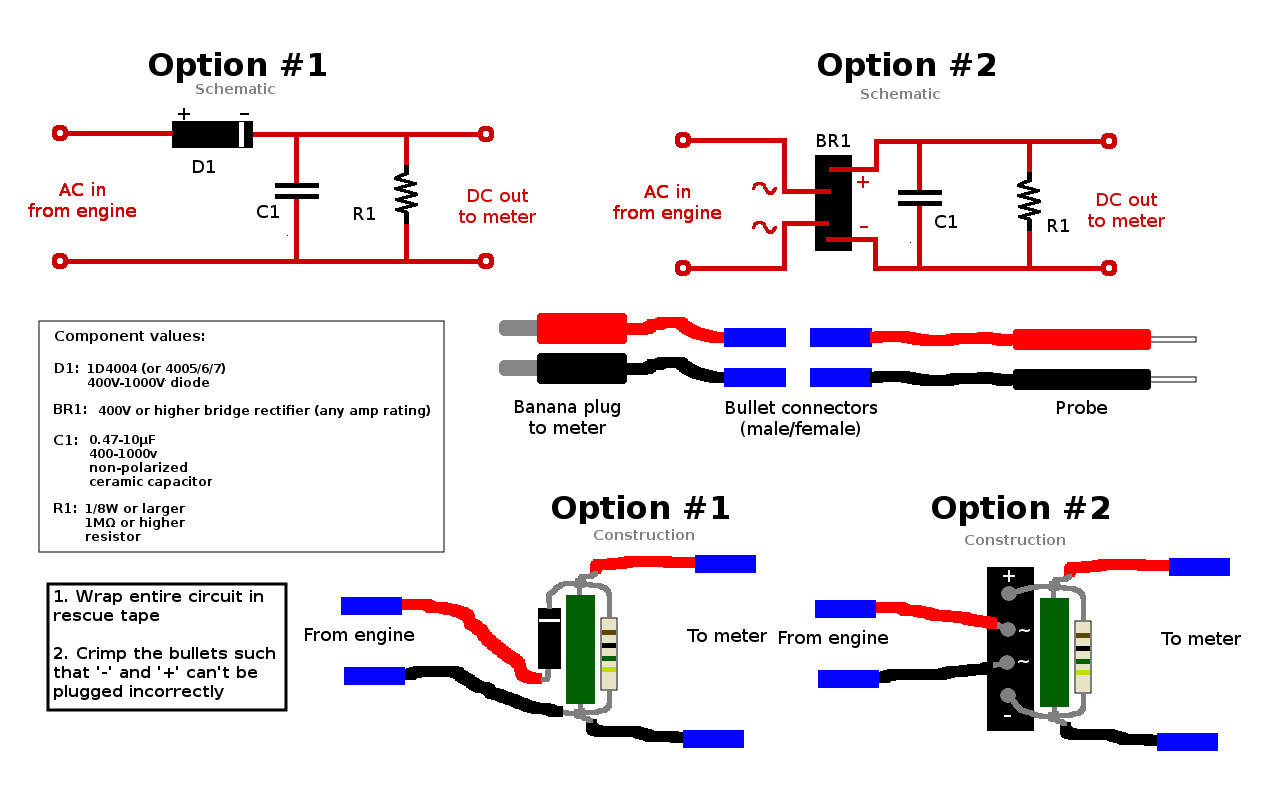
Here are the two possible schematics for a DVA, depending on whether you decide to go with half- or full-wave rectification (single diode or bridge):
To test if you did it right, hook the DVA into your probes, switch your meter to the 200V or higher DC range, and stick your probes into an AC outlet. You should get something close to 170V (peak voltage is Vrms * 1.414, or 120 * 1.414 = 169.68.)
Feel free to let me know if you have any questions, folks!
Theory bits (feel free to skip):
A DVA is nothing more than a rectifier with a little smoothing circuitry following it; i.e., it turns very spiky, low duty-cycle AC (which is what your stator and trigger produce) into pulsating DC (which is what comes out of your switchbox), then flattens the pulses into a steady, measurable DC voltage by storing the peaks. The component values in it are fairly unimportant except for the voltage: since the "load" on the output is nothing but the meter you're using (typically 10MΩ or higher input impedance), and the storage capacitor is recharged more than 30 times per second (say, 300rpm/8 cylinders), the current is going to be in the microamp range and the capacitor value can be anything around 1µF (higher is better; the value determines how much you'll lose off the actual peak, and 1µF loses less than 1 volt in 400 at 30Hz.) The discharge resistor value just needs to be high (1MΩ or more) and the wattage is likewise unimportant due to the low current.
Last - just to help broaden the component choices (or to add to the confusion
In short, whatever you've got on your shelf - or whatever your electronic parts store has on the shelf - will do, even if they haven't restocked recently.
Here are the two possible schematics for a DVA, depending on whether you decide to go with half- or full-wave rectification (single diode or bridge):
To test if you did it right, hook the DVA into your probes, switch your meter to the 200V or higher DC range, and stick your probes into an AC outlet. You should get something close to 170V (peak voltage is Vrms * 1.414, or 120 * 1.414 = 169.68.)
Feel free to let me know if you have any questions, folks!
Last edited:

