CrankyGypsy
Jetboaters Captain
- Messages
- 352
- Reaction score
- 297
- Points
- 217
- Location
- Tampa, FL 33615
- Boat Make
- SeaDoo
- Year
- 2008
- Boat Model
- Challenger
- Boat Length
- 18
i solved an intermittent overheat on one of my engines due to a bad thermosensor (https://jetboaters.net/threads/bad-thermosensor-intermittent-overheat.8032/), but am still getting overheats on both engines during WOT runs over ~5 miles. i suspect that the issue is scale build-up inside the water jackets, particularly calcium carbonates. both engines are doing the same thing at the same rate, so i'm ruling out electrical issues. my temp readings are showing a particularly hot area of the starboard motor around piston #1, leading me to believe there is a mass of calcium/sand/salt there. checking the PWC forums, i ran across this type of blockage a few times. i'll assume it didn't get flushed like it was supposed to by prior owner(s), leading me to wager the internal scale is on the thicker side.
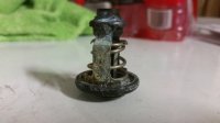
i replaced the thermostats at the beginning of the 2015 season and made 9 trips to the water: 3 in salt and 6 in fresh water. i always flush the engines thoroughly post-salt with Salt-Away during wash down at the house and i will "pre-flush" with fresh water from a spigot before i leave the dock when available. i'm convinced that there is just no way to prevent the accumulation of this gunk. i've also concluded that the factory flush inlet is inadequate to fully fill the waterway components. note that i scraped a little off with my fingernail:
PARTS NEEDED:
- submersible Water Pump (Northern Tool #42358).
- Garden Hose Remnant (Northern Tool #500011).
- 2" PVC Pipe cut to a length of 6-8" (1).
- 2" PVC Cap (2).
- 3" PVC Pipe cut to a length of 2" (3).
- 0.50" x 2" PVC Riser (in the grass sprinkler section) (4).
- 3" to 1.50" PVC Reducer (5).
- 1.50" to 1" PVC Reducer Bushing (6).
- 0.75" Slip x FHT PVC Hose Fitting (in the grass sprinkler section) (7).
- male end of a Garden Hose with about 48" of hose attached (8).
- All Purpose PVC Cement.
- 3/8" ID Tubing about 10' in length.
- 3/4" ID Tubing about 2' to 2.5' needed.
- 1/2" OD Tubing about 2' in length.
- Garden Hose Repair End (Female 5/8" to 3/4"; see pic further down).
- 5 gallon bucket.
- roll of Electrical Tape.
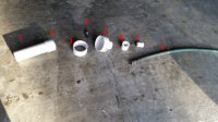
BUILD THE FLUSH ASSEMBLY: assembled parts 3 to 7 in the above pic just as they are laid out with the PVC cement. was careful not to allow the FHT Fitting (7) to seat completely into the back of the 1" Reducer Bushing's (6) recess so it wouldn't glue the spinning collar in-place. then drilled a hole in the large 3" Reducer (5) with the short section of 3" Pipe (3) already glued in. the largest regular bit i have is 5/8" but i think at least a 7/16" drill would've been better. i carefully shaved the threads off one side of the 0.50" Riser (4) with a bench grinder - for it to fit into the 5/8" hole i drilled, i had to get the wall fairly thin. applied cement and tapped it into the 3" Reducer (5) with a mallet.
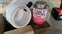
DISASSEMBLE THE EXHAUST: i flushed one engine at a time. started by removing the clean-out plug tray to gain access to each water box and removed their straps. loosened the four hose clamps that secure the aluminum joint with "UP" on it (fiche part #45; referred here after as the "UP Pipe") between the muffler (fiche #36) and the water box. removed the UP Pipe and both rubber collars (fiche #46 & 47) that are attached to either side.
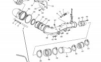
MOVE THE WATER BOXES: back in the clean out area, i unclamped and popped off the large hoses coming off the top of both water boxes. i removed the starboard water box up & out through the tray hole and then slid the port water box back a few inches. i finally unclamped and removed the long, white drain tube that runs from the interior deck to the scupper.
MAKE THE LOOP: placed the 2" PVC Cap (2) onto the short length of 2" PVC Pipe (1) and inserted it into the tail pipe (fiche #43) - this was an attempt to prevent the solution from making its way to the valves. i'm not sure if i have some leaky gaskets under the large 90* elbow (fiche #33) because there was water in here after some of the flushes of both engines, but not all. this is why i switched to a short duration flush with a stronger solution. secured it with Electrical Tape to make it water tight.
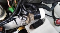
with the UP Pipe (fiche #45) disconnected from the engine, i slipped the Flush Assembly (3-7) over the smaller end of the UP Pipe - i had to use very course grit sandpaper (40grit) to open the inner diameter of the PVC (3) enough to get it to slide over it snugly. with the embossed letters "UP" considered 12 o'clock, i affixed it so the Riser (4) pointed between 9 and 10 o'clock. i used Electrical Tape to secure the Flush Assembly (3-7) to the UP Pipe and make it all water tight. i then added the 3/4" ID Tubing to the Riser (4). the Garden Hose (8) should now be attached.
i slipped the larger rubber exhaust collar (fiche #46) back onto the end of the muffler (fiche #36). i took the entire Flush Assembly (now consisting of parts 3-8, the UP Pipe, and the 3/4" Tubing) and inserted the Garden Hose (8) through the exhaust hole in the stern, ran it over the first water box support bracket, through the hole in the second support bracket, and then outside through the scupper. i plugged the entire Flush Assembly into the rubber muffler collar (fiche #46). while supporting the assembly level, i tightened the two hose clamps.
i removed the two hoses coming from the top and bottom of the thermostat housing. i cut the 3/4" ID Tubing coming off the Flush Assembly's Riser (4) so it was long enough to reach the larger/lower nipple of the thermostat housing. with the correct length measured/cut, i unbolted the housing to remove the thermostat and attached the Tubing to the lower nipple. i remounted the thermostat housing. i attached the 3/8" ID Tubing to the upper nipple on the thermostat housing and ran it up and out to the 5 gallon bucket sitting below the scupper. the purpose for the 3/8" Tubing is to give any excess pressure and solution a route to escape back to the bucket ...not including this will likely cause/worsen back flow into the exhaust.
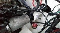
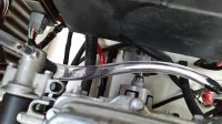
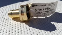
i attached the Female Garden Hose Repair End (see next pic) to the end of the Hose Remnant coming off the Submersible Pump. i disconnected the hose that delivers raw cooling water from the impeller duct to the starboard side of the engine - this will be plugged into the back of the pump plate on the port side. i plugged the Repair End/Hose Remnant into this hose - this will feed the flush solution to the engine from the Submersible Pump. i clamped off the red Yamaha flush inlet hose just above where it and the raw water inlet meet at the y-coupler just inside the engine bay.
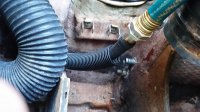
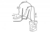
outside, above the bucket of flush solution, i inserted the 1/2" OD Hose into the upper starboard outlet located on the outer-side of the pump plate (the red hose in the next pic) - this connects to the hose (fiche #5) coming off the muffler. finally, i clamped off the hose (fiche #4) that runs out from the huge 90* rubber elbow (fiche #33). the system is now closed-loop and ready for pumping.
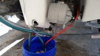
FLUSHING/PUMPING: the engine is not running during this procedure. the Pump delivers solution up the Remnant Hose and into the raw water inlet hose that the boat's jet pump utilizes. this flushes throughout the engine and is returned via the Flush Assembly and the hose plugged into the outside of the jet pump plate. some excess solution may make its way up to the thermostat. i originally tried using the factory flush inlet but found i did not get nearly as much pressure/solution through the system due to that hose's much smaller inner diameter. this was probably not allowing me to fill the entirety of the exhaust jackets. to me, this small diameter hose is a flaw in Yamaha's design which prevents a thorough flush.
FLUSH #1:
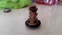
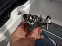
HAMMERHEAD MARINE DESCALER: i mixed one gallon of Hammerhead Marine Descaler with two gallons of water. the solution started out clear but turned yellow about 30mins into the flushing from it dissolving gunk. Hammerhead recommends at least 1.5hrs for flushing. i ultimately decided to do each motor for 3hrs (which could be risky if there is an exhaust leak). here is the starboard thermostat after sitting in the bucket for 45mins:
RINSE: once the three hours were up, i filled a bucket with clean water and pumped that through the same way as the flush to rinse out the solution. during the rinses, i eventually added another garden hose hooked to a spigot with the Yamaha flush adapter to the standard flush inlet under the hatch. feeding both inlets simultaneously, the greater volume helped to push additional bits of larger debris along. i did a total of 5-7 cycles with clean water, catching the water in the bucket and letting the sediment settle. i then skimmed the water off and collected the sediment in a jar. it appeared to be a mix of very fine sand, tiny shell bits, and what looks like brown-green silt you'd find in a pond. it seemed no matter how many rinses i was going to do, the tiny bits would not stop coming out. so after 5-7 times, i called it quits. while putting everything back to normal, i found solution/water had somehow made their way into the main exhaust pipe - maybe i have a leak somewhere? for this reason, i recommend using a stronger solution at a shorter duration as i did below.
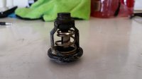
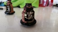
here are before and after pics of the port engine's thermostat (notice the salt-cicle on the coil):
WATER TEST AFTER HAMMERHEAD: (March 3, 2016) i water tested it on Lake Tarpon with the YDS Software. last time out, the air temp was 72*F and the water temp was 62*F. i was consistently tripping the thermosensors (265*F+) after approximately 5 miles of WOT (about 1 pass on Lake Tarpon). if i remember correctly, the engines were running close to the same temps, with the starboard tending to overheat slightly earlier.
this time, the temps were 71* air and 66* water. the starboard motor got up to 220*F quickly (i'm assuming normal operating temps are the standard 212*F) before slowly making it's way to about 245*F and hanging there on multiple passes. the port motor climbed quicker and would take almost 2 passes before tripping the idiot light on the dash. so i'm seeing an improvement over the single pass overheats last time, especially considering the water was 4*F warmer. i spent a few more hours flushing the starboard engine while figuring out better flushing methods, so that may account for it's better improvement?
i also made passes with the thermostats removed, which obviously increased the flow through the system due to noticeably improved cooling readings. this is certainly an option in a pinch, but not something i would want to run consistently because it was putting the engines under optimal operating temperature (guessing 212*F) during cruising even with the issues i am having.
FLUSH #2
decided to do another flush but with something stronger that would only require about 20mins to help reduce the chance of filling the exhaust. after post #13 below, i opted to use sulfamic acid...
SULFAMIC ACID: 4% acid solution with about 1% inhibitor (that's 1lb of sulfamic crystals and 1.5oz of thiourea in 3 gallons of water). flushed for 20 minutes and allowed it to drain. i popped the Flush Assembly and the 2" cap/pipe off to drain any water that made it into the exhaust and reattached them. i immediately flushed the system again for 20 minutes with a 2% neutralizing solution (0.5lb soda ash in 3 gallons of water) to prevent any chance of the acid doing damage. i drained the loop and the exhaust ...and fired the engine up between flush phases for a second just in case. i flushed with some soapy water then several clean flushes with an additional hose feeding the Yamaha flush inlet. again, sediment just kept coming out. i'd estimate that this second flush produced the same amount of crud as the first flush! the solution turned yellow again, so i know it was still finding and dissolving build up.
WATER TEST AFTER SULFAMIC ACID: (March 24, 2016) Lake Tarpon temps at 83* air and 69* water, monitoring the thermosensor with the YDS Software. time was limited, so i only monitored the starboard motor since it was running hotter on my last test out. it took about 3 runs (~15 miles) at WOT to get to around 250*F - this was even an improvement over the first flush. it may have hit the overheat marker with more runs, but that is at least three times the distance prior to flushing AND this was in water 7* warmer.
thermosensors trip at 266*F, causing a limp mode.
CONCLUSION (Spring 2016): it worked, but could it be running cooler? probably. unfortunately, i don't think I busted that supposed blockage around piston #1 on the starboard engine. at this point, i'm tired of this lengthy project and am satisfied enough to leave it until i get the ambition to flush it with the sulfamic acid again. i'd like to think that proper flushing will help, but i believe Yamaha's restrictive flush inlet is inadequate to do a proper/complete job.
UPDATE end of 2016 season: though my outings were limited this year, I had no overheat issues through the 2016 season.
FUTURE CONSIDERATIONS: i plan to do this again (spring 2017), but will order replacement gaskets (fiche #42) and remove the tail pipe (fiche #43) during the flush. i am not sure yet how the internals look, but this should help allow larger debris to flow into the Flush Assembly and out to the bucket. it may also allow the current to flow faster, helping to push crud out.
* * * * *
March 2017: tore down for a second flushing of the engines with the sulfamic solution. despite my thorough post-outing flush procedure, i am noticing build-up from a fairly "short" season, especially at the thermostat. from what i can tell, it is calcium. the tail pipe area also has some fine sand mixed in, giving it a crystallized look that deceptively appeared to be salt. as planned, i removed the tail pipe and the gasket to help carry more sand out of the system. doing both motors took the afternoon.
the flush schedule using the same concentrations as last year:
Sulfamic solution - closed loop - 15mins
Clear system
Clean rinse - open system - 1min
Soda Ash solution - closed loop - 15mins
Clear system
Soapy rinse - closed loop - 1min
Clean rinse w/ additional hose at Yamaha flush adapter - open system - 3mins
Clear System
closed loop = pumping with return hoses fed back to bucket.
clear system = remove "UP" pipe and PVC plug, then fire engine for a few seconds.
open system = pumping, but return hoses emptying to a separate bucket (no loop).
i mixed up the sulfamic solution with very hot water after the flush system was installed. not only did the hot water quickly dissolve the crystals, but i could feel that every area on the engine was getting the solution ....including the suspect water jacket around piston #1 of the starboard engine.
with the tail pipe and gasket removed, the sand was more easily flushed out of the exhaust. i think i got more grit out this time than i managed to get last year, so it is safe to assume the majority of it was trapped in there due to the small pee holes in the tail pipe. with the starboard motor, i could actually hear the sand moving through the exhaust! i am very happy with the amount of crud i removed and feel it was certainly worthwhile to give this another shot.
in regards to the calcium build-up, i am still a little concerned. as i've determined before, i believe the Yamaha flush adapter, the receptacle, and the junction hose are too narrow to provide an adequate fill of the cooling system. therefor, even with Salt-Away, there are going to be areas that the calcium may not be washed away. i just didn't expect it would build up so much in one season. however, maybe the calcium issue at the thermostat is not representative of the entire system: it's likely the thermostat isn't opening during a driveway flush and crud simply ends up depositing there, making the issue seem worse than it really is. maybe pulling the thermostats during every few flushes would help get calcium out (but also further decrease system fill)? do i think i have gotten all of the sand out? doubtful ...maybe another go is in order for next year (as more loosens up).
note about flushing to maximize system fill: for the 2016 season, i started clamping the rearward raw water inlet hose where the junction for the red flush hose is. this prevents a portion of the Salt-Away flush from simply dumping out the strainer in the pump housing. essentially, i am clamping it just as you would if being towed.
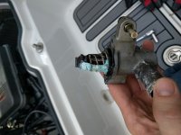
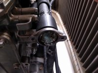
pics prior to flushing:
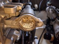
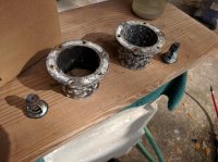
pics post-flush:
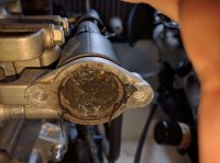
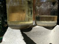
the jars above contain only a small amount of what i flushed out today. the right jar is from the starboard motor after the sulfamic flush. there is a bottom layer of sand, a middle layer of very fine silt (dissolved calcium?), and the top layer of solution.
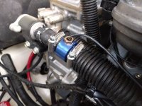
Trail Tech TTO: for added peace of mind and to view something tangible for how well it worked, i installed sensors (part # 732-EH2) near each thermostat to monitor temps from helm gauges. these are a newer version of the ones cybuch installed which can be hooked up to an outside power source, are programmable, have clocks, and are back lit. the 22mm adapter is a very tight fit - i could probably get away without the clamps! there is a 19mm option, but that could be too much of an exact fit to be water tight.
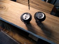
THERMOSTAT MOD: i decided to drill an additional hole in my thermostats. i am not the original owner and the manual does not state how to orient the hole in the thermostats - my guess is they sit at 12-o'clock to allow air to pass out of the system. unfortunately, this causes calcium to settle in the thermostat housing during flushing as the thermostat likely stays closed. i still believe these boats were designed/intended for freshwater use (due to the make-up of the factory anodes and the inadequate flush system), so calcium may never have been an R&D issue. the new hole is 1/16" and i opted to place the larger, original hole at 6-o'clock to help evacuate any minerals.
Calcium content of waters (PPM = mg/L):
Seawater: 400 PPM
Freshwater: ~40 PPM*
*very rough average as waters vary greatly across the US. the range seems to be as low as 0.50 PPM and as high as 90 PPM.
RESULTS: again, i believe i was able to get more crud out this time around with the end of the exhaust removed. i took it out on the lake for a test without the YDS. i am getting TTO temp readings at WOT near the thermostats around 121*F, which matches what cybuch is getting on his. still seeing a higher surface temp on piston #1 of the starboard engine, though it seems to have reduced slightly.
FUTURE CONSIDERATIONS: i would like to modify the flush assembly for a larger output hose diameter and connect directly to the barb on the back of the scupper (rather than run the short garden hose through it), allowing increased system flow. my hopes would be to increase the current to move debris along and to reduce solution backing-up into the exhaust. the downside to this could be that the system empties faster than it can be filled, preventing the sulfamic solution from cleaning the upper surfaces. however, i could install a plastic ball valve on the return hose to restrict flow during acid flushes (calcium) and open it fully during clean water flushes (debris).
i replaced the thermostats at the beginning of the 2015 season and made 9 trips to the water: 3 in salt and 6 in fresh water. i always flush the engines thoroughly post-salt with Salt-Away during wash down at the house and i will "pre-flush" with fresh water from a spigot before i leave the dock when available. i'm convinced that there is just no way to prevent the accumulation of this gunk. i've also concluded that the factory flush inlet is inadequate to fully fill the waterway components. note that i scraped a little off with my fingernail:

PARTS NEEDED:
- submersible Water Pump (Northern Tool #42358).
- Garden Hose Remnant (Northern Tool #500011).
- 2" PVC Pipe cut to a length of 6-8" (1).
- 2" PVC Cap (2).
- 3" PVC Pipe cut to a length of 2" (3).
- 0.50" x 2" PVC Riser (in the grass sprinkler section) (4).
- 3" to 1.50" PVC Reducer (5).
- 1.50" to 1" PVC Reducer Bushing (6).
- 0.75" Slip x FHT PVC Hose Fitting (in the grass sprinkler section) (7).
- male end of a Garden Hose with about 48" of hose attached (8).
- All Purpose PVC Cement.
- 3/8" ID Tubing about 10' in length.
- 3/4" ID Tubing about 2' to 2.5' needed.
- 1/2" OD Tubing about 2' in length.
- Garden Hose Repair End (Female 5/8" to 3/4"; see pic further down).
- 5 gallon bucket.
- roll of Electrical Tape.

BUILD THE FLUSH ASSEMBLY: assembled parts 3 to 7 in the above pic just as they are laid out with the PVC cement. was careful not to allow the FHT Fitting (7) to seat completely into the back of the 1" Reducer Bushing's (6) recess so it wouldn't glue the spinning collar in-place. then drilled a hole in the large 3" Reducer (5) with the short section of 3" Pipe (3) already glued in. the largest regular bit i have is 5/8" but i think at least a 7/16" drill would've been better. i carefully shaved the threads off one side of the 0.50" Riser (4) with a bench grinder - for it to fit into the 5/8" hole i drilled, i had to get the wall fairly thin. applied cement and tapped it into the 3" Reducer (5) with a mallet.

DISASSEMBLE THE EXHAUST: i flushed one engine at a time. started by removing the clean-out plug tray to gain access to each water box and removed their straps. loosened the four hose clamps that secure the aluminum joint with "UP" on it (fiche part #45; referred here after as the "UP Pipe") between the muffler (fiche #36) and the water box. removed the UP Pipe and both rubber collars (fiche #46 & 47) that are attached to either side.

MOVE THE WATER BOXES: back in the clean out area, i unclamped and popped off the large hoses coming off the top of both water boxes. i removed the starboard water box up & out through the tray hole and then slid the port water box back a few inches. i finally unclamped and removed the long, white drain tube that runs from the interior deck to the scupper.
MAKE THE LOOP: placed the 2" PVC Cap (2) onto the short length of 2" PVC Pipe (1) and inserted it into the tail pipe (fiche #43) - this was an attempt to prevent the solution from making its way to the valves. i'm not sure if i have some leaky gaskets under the large 90* elbow (fiche #33) because there was water in here after some of the flushes of both engines, but not all. this is why i switched to a short duration flush with a stronger solution. secured it with Electrical Tape to make it water tight.

with the UP Pipe (fiche #45) disconnected from the engine, i slipped the Flush Assembly (3-7) over the smaller end of the UP Pipe - i had to use very course grit sandpaper (40grit) to open the inner diameter of the PVC (3) enough to get it to slide over it snugly. with the embossed letters "UP" considered 12 o'clock, i affixed it so the Riser (4) pointed between 9 and 10 o'clock. i used Electrical Tape to secure the Flush Assembly (3-7) to the UP Pipe and make it all water tight. i then added the 3/4" ID Tubing to the Riser (4). the Garden Hose (8) should now be attached.
i slipped the larger rubber exhaust collar (fiche #46) back onto the end of the muffler (fiche #36). i took the entire Flush Assembly (now consisting of parts 3-8, the UP Pipe, and the 3/4" Tubing) and inserted the Garden Hose (8) through the exhaust hole in the stern, ran it over the first water box support bracket, through the hole in the second support bracket, and then outside through the scupper. i plugged the entire Flush Assembly into the rubber muffler collar (fiche #46). while supporting the assembly level, i tightened the two hose clamps.
i removed the two hoses coming from the top and bottom of the thermostat housing. i cut the 3/4" ID Tubing coming off the Flush Assembly's Riser (4) so it was long enough to reach the larger/lower nipple of the thermostat housing. with the correct length measured/cut, i unbolted the housing to remove the thermostat and attached the Tubing to the lower nipple. i remounted the thermostat housing. i attached the 3/8" ID Tubing to the upper nipple on the thermostat housing and ran it up and out to the 5 gallon bucket sitting below the scupper. the purpose for the 3/8" Tubing is to give any excess pressure and solution a route to escape back to the bucket ...not including this will likely cause/worsen back flow into the exhaust.


i attached the Female Garden Hose Repair End (see next pic) to the end of the Hose Remnant coming off the Submersible Pump. i disconnected the hose that delivers raw cooling water from the impeller duct to the starboard side of the engine - this will be plugged into the back of the pump plate on the port side. i plugged the Repair End/Hose Remnant into this hose - this will feed the flush solution to the engine from the Submersible Pump. i clamped off the red Yamaha flush inlet hose just above where it and the raw water inlet meet at the y-coupler just inside the engine bay.


outside, above the bucket of flush solution, i inserted the 1/2" OD Hose into the upper starboard outlet located on the outer-side of the pump plate (the red hose in the next pic) - this connects to the hose (fiche #5) coming off the muffler. finally, i clamped off the hose (fiche #4) that runs out from the huge 90* rubber elbow (fiche #33). the system is now closed-loop and ready for pumping.

FLUSHING/PUMPING: the engine is not running during this procedure. the Pump delivers solution up the Remnant Hose and into the raw water inlet hose that the boat's jet pump utilizes. this flushes throughout the engine and is returned via the Flush Assembly and the hose plugged into the outside of the jet pump plate. some excess solution may make its way up to the thermostat. i originally tried using the factory flush inlet but found i did not get nearly as much pressure/solution through the system due to that hose's much smaller inner diameter. this was probably not allowing me to fill the entirety of the exhaust jackets. to me, this small diameter hose is a flaw in Yamaha's design which prevents a thorough flush.
FLUSH #1:
HAMMERHEAD MARINE DESCALER: i mixed one gallon of Hammerhead Marine Descaler with two gallons of water. the solution started out clear but turned yellow about 30mins into the flushing from it dissolving gunk. Hammerhead recommends at least 1.5hrs for flushing. i ultimately decided to do each motor for 3hrs (which could be risky if there is an exhaust leak). here is the starboard thermostat after sitting in the bucket for 45mins:

RINSE: once the three hours were up, i filled a bucket with clean water and pumped that through the same way as the flush to rinse out the solution. during the rinses, i eventually added another garden hose hooked to a spigot with the Yamaha flush adapter to the standard flush inlet under the hatch. feeding both inlets simultaneously, the greater volume helped to push additional bits of larger debris along. i did a total of 5-7 cycles with clean water, catching the water in the bucket and letting the sediment settle. i then skimmed the water off and collected the sediment in a jar. it appeared to be a mix of very fine sand, tiny shell bits, and what looks like brown-green silt you'd find in a pond. it seemed no matter how many rinses i was going to do, the tiny bits would not stop coming out. so after 5-7 times, i called it quits. while putting everything back to normal, i found solution/water had somehow made their way into the main exhaust pipe - maybe i have a leak somewhere? for this reason, i recommend using a stronger solution at a shorter duration as i did below.
here are before and after pics of the port engine's thermostat (notice the salt-cicle on the coil):


WATER TEST AFTER HAMMERHEAD: (March 3, 2016) i water tested it on Lake Tarpon with the YDS Software. last time out, the air temp was 72*F and the water temp was 62*F. i was consistently tripping the thermosensors (265*F+) after approximately 5 miles of WOT (about 1 pass on Lake Tarpon). if i remember correctly, the engines were running close to the same temps, with the starboard tending to overheat slightly earlier.
this time, the temps were 71* air and 66* water. the starboard motor got up to 220*F quickly (i'm assuming normal operating temps are the standard 212*F) before slowly making it's way to about 245*F and hanging there on multiple passes. the port motor climbed quicker and would take almost 2 passes before tripping the idiot light on the dash. so i'm seeing an improvement over the single pass overheats last time, especially considering the water was 4*F warmer. i spent a few more hours flushing the starboard engine while figuring out better flushing methods, so that may account for it's better improvement?
i also made passes with the thermostats removed, which obviously increased the flow through the system due to noticeably improved cooling readings. this is certainly an option in a pinch, but not something i would want to run consistently because it was putting the engines under optimal operating temperature (guessing 212*F) during cruising even with the issues i am having.
FLUSH #2
decided to do another flush but with something stronger that would only require about 20mins to help reduce the chance of filling the exhaust. after post #13 below, i opted to use sulfamic acid...
SULFAMIC ACID: 4% acid solution with about 1% inhibitor (that's 1lb of sulfamic crystals and 1.5oz of thiourea in 3 gallons of water). flushed for 20 minutes and allowed it to drain. i popped the Flush Assembly and the 2" cap/pipe off to drain any water that made it into the exhaust and reattached them. i immediately flushed the system again for 20 minutes with a 2% neutralizing solution (0.5lb soda ash in 3 gallons of water) to prevent any chance of the acid doing damage. i drained the loop and the exhaust ...and fired the engine up between flush phases for a second just in case. i flushed with some soapy water then several clean flushes with an additional hose feeding the Yamaha flush inlet. again, sediment just kept coming out. i'd estimate that this second flush produced the same amount of crud as the first flush! the solution turned yellow again, so i know it was still finding and dissolving build up.
WATER TEST AFTER SULFAMIC ACID: (March 24, 2016) Lake Tarpon temps at 83* air and 69* water, monitoring the thermosensor with the YDS Software. time was limited, so i only monitored the starboard motor since it was running hotter on my last test out. it took about 3 runs (~15 miles) at WOT to get to around 250*F - this was even an improvement over the first flush. it may have hit the overheat marker with more runs, but that is at least three times the distance prior to flushing AND this was in water 7* warmer.
thermosensors trip at 266*F, causing a limp mode.
CONCLUSION (Spring 2016): it worked, but could it be running cooler? probably. unfortunately, i don't think I busted that supposed blockage around piston #1 on the starboard engine. at this point, i'm tired of this lengthy project and am satisfied enough to leave it until i get the ambition to flush it with the sulfamic acid again. i'd like to think that proper flushing will help, but i believe Yamaha's restrictive flush inlet is inadequate to do a proper/complete job.
UPDATE end of 2016 season: though my outings were limited this year, I had no overheat issues through the 2016 season.
FUTURE CONSIDERATIONS: i plan to do this again (spring 2017), but will order replacement gaskets (fiche #42) and remove the tail pipe (fiche #43) during the flush. i am not sure yet how the internals look, but this should help allow larger debris to flow into the Flush Assembly and out to the bucket. it may also allow the current to flow faster, helping to push crud out.
* * * * *
March 2017: tore down for a second flushing of the engines with the sulfamic solution. despite my thorough post-outing flush procedure, i am noticing build-up from a fairly "short" season, especially at the thermostat. from what i can tell, it is calcium. the tail pipe area also has some fine sand mixed in, giving it a crystallized look that deceptively appeared to be salt. as planned, i removed the tail pipe and the gasket to help carry more sand out of the system. doing both motors took the afternoon.
the flush schedule using the same concentrations as last year:
Sulfamic solution - closed loop - 15mins
Clear system
Clean rinse - open system - 1min
Soda Ash solution - closed loop - 15mins
Clear system
Soapy rinse - closed loop - 1min
Clean rinse w/ additional hose at Yamaha flush adapter - open system - 3mins
Clear System
closed loop = pumping with return hoses fed back to bucket.
clear system = remove "UP" pipe and PVC plug, then fire engine for a few seconds.
open system = pumping, but return hoses emptying to a separate bucket (no loop).
i mixed up the sulfamic solution with very hot water after the flush system was installed. not only did the hot water quickly dissolve the crystals, but i could feel that every area on the engine was getting the solution ....including the suspect water jacket around piston #1 of the starboard engine.
with the tail pipe and gasket removed, the sand was more easily flushed out of the exhaust. i think i got more grit out this time than i managed to get last year, so it is safe to assume the majority of it was trapped in there due to the small pee holes in the tail pipe. with the starboard motor, i could actually hear the sand moving through the exhaust! i am very happy with the amount of crud i removed and feel it was certainly worthwhile to give this another shot.
in regards to the calcium build-up, i am still a little concerned. as i've determined before, i believe the Yamaha flush adapter, the receptacle, and the junction hose are too narrow to provide an adequate fill of the cooling system. therefor, even with Salt-Away, there are going to be areas that the calcium may not be washed away. i just didn't expect it would build up so much in one season. however, maybe the calcium issue at the thermostat is not representative of the entire system: it's likely the thermostat isn't opening during a driveway flush and crud simply ends up depositing there, making the issue seem worse than it really is. maybe pulling the thermostats during every few flushes would help get calcium out (but also further decrease system fill)? do i think i have gotten all of the sand out? doubtful ...maybe another go is in order for next year (as more loosens up).
note about flushing to maximize system fill: for the 2016 season, i started clamping the rearward raw water inlet hose where the junction for the red flush hose is. this prevents a portion of the Salt-Away flush from simply dumping out the strainer in the pump housing. essentially, i am clamping it just as you would if being towed.
pics prior to flushing:


pics post-flush:


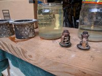
the jars above contain only a small amount of what i flushed out today. the right jar is from the starboard motor after the sulfamic flush. there is a bottom layer of sand, a middle layer of very fine silt (dissolved calcium?), and the top layer of solution.
Trail Tech TTO: for added peace of mind and to view something tangible for how well it worked, i installed sensors (part # 732-EH2) near each thermostat to monitor temps from helm gauges. these are a newer version of the ones cybuch installed which can be hooked up to an outside power source, are programmable, have clocks, and are back lit. the 22mm adapter is a very tight fit - i could probably get away without the clamps! there is a 19mm option, but that could be too much of an exact fit to be water tight.

THERMOSTAT MOD: i decided to drill an additional hole in my thermostats. i am not the original owner and the manual does not state how to orient the hole in the thermostats - my guess is they sit at 12-o'clock to allow air to pass out of the system. unfortunately, this causes calcium to settle in the thermostat housing during flushing as the thermostat likely stays closed. i still believe these boats were designed/intended for freshwater use (due to the make-up of the factory anodes and the inadequate flush system), so calcium may never have been an R&D issue. the new hole is 1/16" and i opted to place the larger, original hole at 6-o'clock to help evacuate any minerals.
Calcium content of waters (PPM = mg/L):
Seawater: 400 PPM
Freshwater: ~40 PPM*
*very rough average as waters vary greatly across the US. the range seems to be as low as 0.50 PPM and as high as 90 PPM.

RESULTS: again, i believe i was able to get more crud out this time around with the end of the exhaust removed. i took it out on the lake for a test without the YDS. i am getting TTO temp readings at WOT near the thermostats around 121*F, which matches what cybuch is getting on his. still seeing a higher surface temp on piston #1 of the starboard engine, though it seems to have reduced slightly.
FUTURE CONSIDERATIONS: i would like to modify the flush assembly for a larger output hose diameter and connect directly to the barb on the back of the scupper (rather than run the short garden hose through it), allowing increased system flow. my hopes would be to increase the current to move debris along and to reduce solution backing-up into the exhaust. the downside to this could be that the system empties faster than it can be filled, preventing the sulfamic solution from cleaning the upper surfaces. however, i could install a plastic ball valve on the return hose to restrict flow during acid flushes (calcium) and open it fully during clean water flushes (debris).
Last edited:

