• Welcome to Jetboaters.net!

    We are delighted you have found your way to the best Jet Boaters Forum on the internet! Please consider Signing Up so that you can enjoy all the features and offers on the forum. We have members with boats from all the major manufacturers including Yamaha, Seadoo, Scarab and Chaparral. We don't email you SPAM, and the site is totally non-commercial. So what's to lose? IT IS FREE!

    Membership allows you to ask questions (no matter how mundane), meet up with other jet boaters, see full images (not just thumbnails), browse the member map and qualifies you for members only discounts offered by vendors who run specials for our members only! (It also gets rid of this banner!)

    free hit counter

Challenger 180 anti-porpoising modification

CrankyGypsy

Jetboaters Captain
Messages
352
Reaction score
297
Points
202
Location
Tampa, FL 33615
Boat Make
SeaDoo
Year
2008
Boat Model
Challenger
Boat Length
18
(referencing 2008 Sea Doo Challenger 180)
(Porpoising C180 - Trim tabs or pump wedge?)
(Speedster 200 Trim options - porposing)

If you own a 2005-2008 Challenger 180, you know that they come out of the water easily over waves. "Porpoising" forces you to slow down and is a huge nuisance when you want to get somewhere fast. Sea Doo addressed this issue for 2009 and those owners report less issues due to flatter and wider chines. To help the earlier 180s, they offered a pair of small trim tabs for $475 and sometimes covered them under warranty. These OEM accessories are no longer available (selling out in 2009!) and the layout of the stern prevents common trim tabs from being installed without detriment to reverse functionality.

Right now, I am just posting up a basic overview of the plate as I haven't had a chance to test it out on The Gulf against swells. Regardless if this works or not, I want it documented for anyone else considering solutions to this problem. If further tests prove positive, I will elaborate on the design and fabrication in the following post. My initial testing on Lake Tarpon seems to show an expected 1-2mph reduction in top speed. One benefit I may be noticing on the lake is the boat remaining on plane a little longer as I reduce speed.
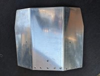
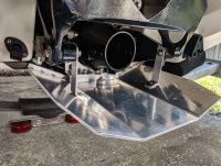
IMG_20190728_164408.jpg IMG_20190728_170152.jpg IMG_20190728_170311.jpg
 
(reserved)
 
(referencing 2008 Sea Doo Challenger 180)
(Porpoising C180 - Trim tabs or pump wedge?)
(Speedster 200 Trim options - porposing)

If you own a 2005-2008 Challenger 180, you know that they come out of the water easily over waves. "Porpoising" forces you to slow down and is a huge nuisance when you want to get somewhere fast. Sea Doo addressed this issue for 2009 and those owners report less issues due to flatter and wider chines. To help the earlier 180s, they offered a pair of small trim tabs for $475 and sometimes covered them under warranty. These OEM accessories are no longer available (selling out in 2009!) and the layout of the stern prevents common trim tabs from being installed without detriment to reverse functionality.

Right now, I am just posting up a basic overview of the plate as I haven't had a chance to test it out on The Gulf against swells. Regardless if this works or not, I want it documented for anyone else considering solutions to this problem. If further tests prove positive, I will elaborate on the design and fabrication in the following post. My initial testing on Lake Tarpon seems to show an expected 1-2mph reduction in top speed. One benefit I may be noticing on the lake is the boat remaining on plane a little longer as I reduce speed.
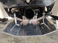
View attachment 102177 View attachment 102178 View attachment 102179
Neat!
This may be a case where top speed may suffer but you can reach the new speeds more often!
Plate looks sharp man!love the idea
 
UPDATE: I'm not really happy with the overall results of the large plate that I fabricated. My tests have been on a lake, so I'll probably be less impressed in The Gulf. It does seem to help a little, but I had to remove my Cobra Fins to run the plate. I also don't like that I have to remove the plate to do a coolant change. I originally wanted to replicate the tabs Sea-Doo offered, but I don't have the means to do it on my own, nor did I want to shell out the cash for someone to make them for me out of an expensive chunk of aluminum.

NEW PLAN: I figured out a way I can do most of the build of the Sea-Doo tabs on my own, each assembled from two cheaper sections of aluminum. I emailed Sea-Doo and they quickly sent me the installation pdf of their discontinued kit. Between this and the very few photos available online, I figured out rough dimensions and got the metal ordered. I have attached the pdf of this kit* and will update again once I make some progress.

*the Sea-Doo kit also included an additional part and directions for a "pump support bracket" that I believe was only applicable on the models with weedless grate systems (2005-2006).
 

Attachments

Been sidetracked a lot, but finally finished the fab on these. I haven’t attached or tested the trim tabs yet, but here is the supply information.

METAL:
(2x) 6”x6” 10 gauge Stainless Steel 304 2B
(2x) 3.75”x0.50”x4” Aluminum 6061
(2x) 6”x0.75”x1.25” Aluminum 6061

STAINLESS HARDWARE:
(6x) #14 1.50” Oval Head Wood Screw
(12x) M6x1.00 16mm Flat Socket Head
(2x) M8x1.25 55mm Hex Head Bolt
(2x) M8x1.25 Hex Nut
(4x) M5x0.80 25mm Socket Head

OPTIONAL:
(2x) Zinc Anode (I used Sea Doo 271001813)
(2x) M5-0.80 25mm Button Head (stainless steel)

SUPPLIES:
Drill Set
Center Drill Set
1/2” Zero Flute Countersink
M5 Counterbore
M6 Counterbore
Cutting Fluid
Loctite 243
Silicone

TOOLS:
Drill Press
Drill Press Vice
Metric Tap Set

Notes: the instructions do not make this perfectly clear, but the M8 bolt is not designed to ever bend the stainless plate. The proper way to adjust the trim is to leave the six M6 screws loose, turn the M8 to the desired depth, add Loctite, then tighten. If an adjustment needs made, loosen the M6 screws and adjust again. Regarding the pattern that I included here, be sure to print this at "actual size."

tabs.jpg
 

Attachments

Last edited:
WORK N PROGRESS: the tabs that I fabricated are not exact duplicates of the Sea-Doo tabs (however, see the next post for how I modified these to duplicate the Sea Doos). My tabs are simpler, each made from two pieces of flat bar aluminum that is cut on a bandsaw at approximately 90degrees, whereas the Sea-Doo tabs are milled from a block of aluminum that has an angled mounting surface. Because of this, my tabs currently have a minimum trailing edge depth around 3/4” to 7/8” but Sea-Doo “recommends” that the max depth be 3/8”. I do not have any trim tab experience, so I naively thought of this recommendation as a safety precaution to prevent submarining. However, my test in light chop has me thinking too steep is as bad as not having them at all: although the boat was not porpoising, it seemed like the tabs were causing the bow to slam into the next wave. That, or I’m simply expecting too much from an 18’ boat? In any case, I plan to remove them and have a machinist shave them to reduce the trailing edge depth, then I’ll update with results. Here is the fabrication process:

I printed copies of my plans, cut them out, and gave the paper patterns to one of the metal supplier employees to cut all my angles and bend the stainless. I cleaned these up a little with a belt sander and a fine file, then used the patterns to transfer the drill locations. All drilling was done on my press with the lowest setting (300RPM) and using plenty of cutting oil.

20200604_163650.jpg

Clamping the stainless plate, I drilled the six holes one at a time with a center drill, then worked up a few steps to a 9/32” bit. Then I cut a clean 82degree recess with a zero flute countersink. Once it was cut deep enough for a flush fitment of the screw, I flipped it over and used the M6 counterbore to level out the burr. Then I re-clamped, drilled, and countersunk the next.

20200611_170321.jpg 20200611_171433.jpg 20200611_171645.jpg

(see next post before going further - the base needs milled at an angle to get a proper trailing edge) The base piece requires a lot of drill bit swapping. I again clamped and completed each hole before moving to the next. I started with the three large mounting holes, step-drilling them to 17/64” and countersinking them with the 1/2” zero flute until the angle of the countersink began about 3/16” below the surface. Next I drilled for the M5 bolts that hold the two pieces of aluminum together, using a 7/32” bit (or a [HASH=528]#5)[/HASH]. These were counterbored so the socket head sits flush inside. The six holes on the bottom were drilled to 13/64” diameter and about 5/8” deep, then countersunk slightly, and threaded with a M6x1.00 tap. I checked that the countersink was deep enough to allow the flat heads to snug tightly onto the stainless plate.

20200617_152241.jpg 20200617_160932.jpg
20200617_173111.jpg 20200617_183323.jpg 20200623_105831.jpg

For the thinner piece of aluminum, I measured and transferred the previously drilled locations of the M5 bolts on the base piece to this piece. Then I placed it in a vice, leveled it against the drill press surface, and drilled two holes about an inch deep using a 11/64” bit. The single hole for the large adjustment bolt was drilled 17/64” and threaded with a M8x1.25 tap.

20200617_190510.jpg

The M5 bolts hold the two aluminum pieces together. I originally had planned to then take this to my welder to strengthen these joints, but I later decided it wasn’t necessary due to the design: loosen the six flat heads, adjust the M8 to the desired depth, then tighten the flat heads. This way, there isn’t as much force acting on the aluminum as I had initially thought it would. And since my tabs start at a lower depth, I didn’t really need the adjustability...

20200616_205047.jpg

I placed rubber vacuum caps on the M8 bolt ends to prevent the bolts from digging into the plate. For my install, I tightened the six flat heads on each tab before adjusting the M8 to just barely touch the stainless plate. As mentioned above, this gave my tab a trailing edge depth of around 7/8” below the trailing edge of the boat. In this fashion, the M8 is not holding the plate into a steeper position, but rather prevents the plate from vibrating. Knowing this now, I’m wondering if the second section of aluminum could possibly be omitted since additional depth will likely never be needed?

My boat and/or band saw edge were steeper on my port side bracket, causing that trailing edge to be almost 1/4” deeper than than the starboard. To compensate and match the trailing edge to the starboard side’s plate, I used two strips of plastic (cut from a greek yogurt carton) to slightly shim the lower edge of the mounting bracket away from the boat. I abraded the shims with sandpaper and used 3M spray adhesive to secure them.

20200707_183724.jpg 20200707_184023.jpg 20200707_184154.jpg 20200707_184114.jpg

After my initial test on light chop in The Gulf (the trailing edge of 7/8" may be too steep), I’m removing them and taking the mounting base to my local machinist (if he’s still taking jobs during this pandemic) to “bevel” the bottom, plate-mounting edge. This should reduce the trailing edge depth to within SeaDoo recommendations (3/8" max). Hopefully, this will allow the boat to float over the waves better.
 
Last edited:
FINAL IMPROVEMENTS: To get a trailing edge that starts level with the running surface of the hull, I took my base pieces to a machinist. I had him square the band saw cuts and then mill an angled surface on the large face of the base that mounts to the hull. This forced me to repair the six mounting holes in my hull and redrill them to match the new angle of the milled bracket. This works but causes a less than desirable screw angle for my trim tabs, so I advise using the following method for Sea Doo specs...

Ideally, take the large base that is fresh off the band saw, then transfer and drill the six threaded holes in the bottom, plus the two small clearance holes with their counterbores on each base blank. Next, have the machinist angle the mounting surface of the aluminum bases by removing 7/32” at the top edge (see drawing below). Once this angle is milled, go back on the drill press and re-counterbore the two small clearance holes to allow the M5 socket caps to be flush again. Now, moving to the three 17/64” mounting holes, clamp the non-milled surface facing up (newly-milled surface facing down and flat against the vice). Drilling these three countersunk holes might get tricky due to the angled surface once in the vice.* Plus, it might take some ingenuity to secure the now-angled block in there, although I was able to secure mine after they were milled with no issue. Clamp and complete each one before moving to the next. Patiently graduating from smaller center drills up to a 1/4” center drill should allow the drill bits to start true against this angled surface - this will make the three holes perpendicular to the hull surface as Sea Doo intended. Finish each with the zero-flute countersink before moving on to the next 17/64” hole.

* If you can’t get the drills to bite correctly on an angle, you can just do as I did in the previous post and drill them perpendicular to the outer face. Just remember to account for this angle when drilling the hull since the instructions indicate to drill perpendicular.

20200804_102423.jpg

This next drawing shows what I had the machinist do. He squared-off the band saw cuts to secure it accurately in the vice and improve the stainless plate mounting surface, then he milled the angle to have 7/32” of material removed at the top edge.

milled.JPG

I also added a Sea Doo zinc anode (part 271001813) to each trim tab since salt had crystallized on my tabs during the short four hours I was in The Gulf on my initial test. I offset these so they did not interfere with access to the center mounting screw. I used an M5-0.8 x 25mm button head to secure the anodes to the underside of the adjustment plate.

Due to the hull variation between the two sides, I took my shim from the port side on the previous trial and flipped it on the starboard side. This isn't necessary, it just gets both trailing edges starting even when the plates are mounted flat to the bottom of the base.

20200806_131335.jpg
 
Nice work on this, and your first version is very similar to what we used on our older model challenger.

The previous hull, the 2000-2003 Challenger 1800/2000/X20 would porpoise as well. Without bow weight, you had a rough ride above 40mph. So one of the guys in the the Seadoo Forum named Aquaman (screen name) created a ride plate for these hulls.

It mounted to the Mercury SportJet and extended it out. We shimmed it with longer bolts and nuts. Which we could adjust to our liking. Whatever speed we scrubbed off top on smooth water, we gained back in spades in any wavy water, as the hull would cut waves like a beast! It worked great.

Same here, I had to have mine made a bit shorter, as it had to clear our CobraJet Steering Fins. And even shorter, it performed well.

It was sort of stressful on that hardware, as I would shear a bolt annually. There is a ton of force (literally) on that hardware.

Good luck, I will be following along, as I hope your invention does as good or better job!
 
@biffdotorg Yup, his was one of the first ones I ran across. I just went back and saw your posts: wow, you guys were running fairly deep trailing edges with them. My original, giant plate was a copy of Mb185cs's on that forum. It isn't adjustable and had a fraction of your depth. I opted to ditch it to reinstall fins before testing it out on The Gulf. My next test with the Sea Doo copies will have a shallow trailing edge since 3/4" seemed too much.

You've got me concerned about shearing hardware, now! haha. The aluminum parts on mine are held together with two M5 bolts... we'll see how they hold up. Hopefully the design of the flat socket heads securing the SS plate alleviate most of that stress.
 
Left out of Bayport, FL yesterday for scalloping. Full tank of gas and no more than 700lbs in people and gear. Set the trailing edge of the tabs to about 3/16". Hardware held up under some rough conditions:

Heading out, waves were around a moderate chop (marine report calling it 2-3' waves, but I wouldn't) and we were kind of stuck doing around 28mph to prevent leaping out of the water on the occasional higher swell. This seems to be better than the day I bought it and had to run it up Tampa Bay to my trailer as it felt like it was nose-up the entire time. Storm moved right in on top of us (15mph winds with rain), so we went back to the ramp (6miles run) - again, still doing 25-30mph in crappier weather. I'm thinking that's not too bad for it being light and short? I may recall my AR230 leaping out over bigger swells just above that speed, so seems to be a fair expectation for this smaller boat. I also remember my AR230 landing better, maybe? That probably has to do with the weight allowing the Yamaha to plow into the next wave, while the Challenger kind of bounces off of it.
The clouds broke, the wind died, and the water calmed down to a very mild chop, so we went back out. I was almost expecting that teeth-chattering "rumble strip" sensation from these small waves slapping the hull, but we were able to cruise at 40mph+ as if it was smooth as glass.

I'm not sure by how much, but it seems better. I've put a lot of hours into this project and am kind of ready to call it quits with the R&D. haha. I've accepted that it's never going to compare to my old AR230, so I'm content at leaving the tabs set at this depth (for now) and move on to other projects.

Do I recommend these BRP-style tabs? In other words, would I make a set if I bought another C180?
Yes, because the next time I would only have to build them once ...and also drill my hull once.
 
Back
Top