• Welcome to Jetboaters.net!

    We are delighted you have found your way to the best Jet Boaters Forum on the internet! Please consider Signing Up so that you can enjoy all the features and offers on the forum. We have members with boats from all the major manufacturers including Yamaha, Seadoo, Scarab and Chaparral. We don't email you SPAM, and the site is totally non-commercial. So what's to lose? IT IS FREE!

    Membership allows you to ask questions (no matter how mundane), meet up with other jet boaters, see full images (not just thumbnails), browse the member map and qualifies you for members only discounts offered by vendors who run specials for our members only! (It also gets rid of this banner!)

    free hit counter

KXCam22 AR230 Computer Controlled Ballast Build

KXCam22

Jetboaters Admiral
Messages
1,084
Reaction score
908
Points
272
Location
Kamloops BC
Boat Make
Yamaha
Year
2008
Boat Model
AR
Boat Length
23
By request I am reposting the details of my ballast build for the 2008 AR230. I have been using the system for 3 summers now with great success. There were a few minor issues and a couple of my ideas didn't workout but with a few tweaks the system works excellently. Fill time is approx 5 minutes.

My build was typical to many in terms of bags, location and such but I added some additional equipment that many won't' I will warn you now that I am an electrical engineer, so I have a tendency to make things as fancy and cool as possible. Here goes:
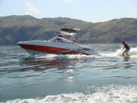
072.JPG

I started with a game plan:
- 2 pumps
- 3 bags
- electric valves to control the flow of water.
- fully automated to turn off when empty and full
- computer control with touch screen
- audible warning when it turns off
- fast fill times.
- as few holes in the hull as possible.

I got all my main parts at Wakemakers.

Bags:
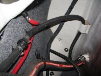
I used the typical twin 400lbs bags in the side compartments and an 800lb in the ski locker. I have since added an 800 sumo sac aux. bag that sits on the swim deck or on the floor. We fill that one with an aux. hose and quick connector from the pump system. Preparing the inside of the rear compartments was nasty. There are a number of sharp screws in there that are not removable. I am not a small person and there is a shortage of midgets or slave children in the area so I had to crawl in there myself with a grinder and grind all the screw points off. I then installed the bags and used some vinyl decking material as a cocoon to padd the bags. Works great. All of my bags have a fly-high quick connect. It has proven to be very handy and worth installing. For the port side you have to relocate the battery and the filler hose. The battery is simple as you just move it forward 12" and re-attach, then extend the battery cables. For the filler hose I installed an eye-bolt up very high in the side wooden bulkhead and then used large ty wraps to pull the filler hose up and out of the way.
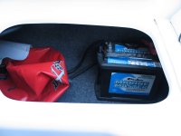
relocated battery_resize.JPG

relocated filler hose.JPG


More to come. Cam.
 
Last edited:
Pumps and water intake:
Notable successes: Using 1" automotive heater hose.

Probably the most difficult task is the installation of the water intake since there is not much room to work with. You must do some research to verify that your intake size will flow enough water to
support the pumps you plan to use. I use two johnson pumps which flow 13 GPM each. This gives 13*2*60=1560 GPH. I used a 1-1/2" through hull intake which is capable of flowing 5800GPM giving me a 3.78x safety margin. Of course this flow gets reduced by the fittings you use after the through hull intake fitting but I have enough flow margin.
exh support in place_resize.JPG

header 2_resize.JPG
Here is the completed throughhull water intake. I debated using the shutoff valve for 2 reasons. Although it is required by YABC code, most of the attached piping is above water line and it is very inaccessible so likely I would be the only person who could use it in an emergency. As you can see it makes fitting everything tight. One issue with almost all through hull fitting is that they are straight thread and any other fittings are pipe type with tapered threads. I cut 1" off my through hull and re-threaded the end to be tapered. I added a support piece for the muffler. You can see the spigot where the starboard supply hose connects. I used 1" automotive heater hose for the main supply connection due to the heat in this area. This proved to be an inexpensive and excellent choice - I would use it almost everywhere next time.
port feed hose_resize.JPG
mounted throughull_resize.JPG
Here you can see the starboard feed hose attached to the manifold tee. In conclusion, the intake install was a pain. If I was to do this again I would use dual 1" fittings with a spigot end and attach my feed hoses directly with no shutoff valve. To make the pumps easy to install I mounted them on a board as an assembly with the valves. I used the Jackson Pollock effect to add some life to it.
pump 002_s.JPG

Once mounted the pumps and valves are easy to access and wire. Here is one in place.
port pump wired 2_resize.JPG
starb pump1_resize.JPG

A note on the valves. These valve didn't workout. The pump puts out enough suction to pull these valve closed - fill but not drain. What is required is an electric ball valve. My quick fix was just to replumb them so that one pump fills the rear bags and the 2nd pump fills the center bag and the aux bag. I have ball valves for the aux bag now. This was the only planned item of my system that didnt work out. The electric ball valves make it work.
More to come. Cam.
 
Last edited:
Venting:
To fill, the air has to be vented out of the bag. Water flowing out of the vent is also a prime way of determining that the bags are full. The only design issue to watch for is siphoning. What can happen as your boat leans over in a turn is that the water starts a siphon and drains itself out through the vent. You can buy fancy anti-siphoning loops but with some careful design they are not required. The first main method it to route your vent to the opposite side of the boat. That way when the boat leans the opposite side vent is raised. I did something completely different that required NO hull holes. I also wanted this system to shut off automatically when filled which requires a level switch of some kind. I designed and built a cheap vent mount level switch system. All 3 of my vent use the same high level switch. For the rear bags, to me the most obvious (and easy) place to vent the bags is behind the swim deck seat cushions. It is high enough to prevent siphoning, no hull hole required, hidden and easy to work on.

port rearbag vent fitting_resize.JPGHLSW on rear vent line starb_resize.JPG
This is the completed starboard vent with high level switch. As you can see the vent fitting drains from behind the cushion. You can use this location without the level switch since when you see water trickling on teh deck you know the bags are full. I use an identical level switch at the bag inlet to determine when it is empty. They work great. On my touch screen interface they show up as icons for level and have a 0-100% bar graph that show how full the bag is. I vented the ski locker bag to the cooler drain, so again no new hull hole required.

More to come. Cam.
 
Computer Controls:
Here is where the fun starts. I used a mini 12V PLC to control the overall ballast system with a 4" touch screen interface. The cost of this equipment is offset by not having to buy pump timers and 4 dash switches. Not quite a wash in terms of cost but infinitely cool and I can modify the screens at any time. I get to take my laptop boating. I started out using a few different shades of color but found that they were hard to read in full sunlight. I switched them to a dark/light motif which is easy to see in sunlight. Here are some of the screens.
ballast screen master.jpg ballast center.jpg ballast rear.jpg
ballast Sumo.jpg

The bar graph show the stat of fill of the bags and the black squares at each end are the limit switches. The F and D buttons are fill and drain. The arrow returns to the previous menu. The outputs of the PLC are not rated high enough for the pumps so a fwd and rev relay is used for each pump. All of the wiring is contained in a box mounted inside the helm compartment.

IMG_2702.JPG
The touchscreen is mounted just above the throttle levers for easy access.

DSCN0866.JPG

And there you have it, my complete system. It works fantastic and give fill times of less than five minutes. Right now the L & R bags are plumbed together. Eventually I will re-plumb it back to my original design so I can alter the weight on each side of the boat on the fly. So far we dont bother just fill to the max and surf. The only thing I forgot in my design was some winterizing fitting so I can blow out the hoses with compressed air. It was a bit of work but is now so nice to use and make surfing a blast. Hope this help someone with their system install. Cam.
 
Thanks, that was a great write up,
 
Pure awesomeness :winkingthumbsup" :thumbsup:
 
Great write up Cam.
Is the PLC taking the shock and vibration ok?
Those look like solid state relays. Any problem with them?
How much did the plant Maintenance Department get involved?:)
 
Cam, wakemakers is against using the same inlet for multiple pumps and state it voids their warranty. I'm a big fan of limiting the # of inlets (holes) going into the boat but don't want to end up with problems. What was your overall thought process with your inlet setup?
 
I originally looked at using the Tsunami pumps. They are incredibly cheap and have excellent flow rates. However, you need 2 pumps per bag, a fill and a drain. On the Yamaha you cant use the Tsunami pump for filling purposes since it must be below water line to prime, and there is no practical location on the boat where it can be mounted below the water line. The drain is no problem.
I am surprised to hear they are against a single inlet. What warranty does it void? When I did mine they were quite happy with one. Perhaps people are trying to run 2 pumps off a single 1" which could starve the pumps. In traditional engineering design, as long as the GPM flow capacity of the fitting and pipework is equal or greater than the GPM requirement of the pumps then there should be no issues. In my case I have 3.78x extra flow capacity available. The flow in pipes is reduced by friction of the flow on the walls, hence the larger the diameter of the pipe, the much larger the flow capacity. If you look at simple area, a 1.5" pipe has an cross-sectional area of 1.67 sq.in while a 2ea 1" inlets together are s*0.78 sq.in= 1.57 sq.in. The 2 ea 1" inlets together are smaller in area and have more surface friction. This is some recommendations off the Wakemakers site. As you can see they would allow 2 impeller pumps on a single 1" which I would not expect to perform well. One other aspect that is never mentioned, but helps, is that the installed fitting is about 12" below the surface of the water which adds 1/2" psi of pressure to help the water go in.

flowchart.jpg
The only issue I ran into was the physical size of the 1.5" fittings, 90s etc, and fitting them into the tight space. It took some thought but I am very happy with the routing of mine. If I was doing another Yamaha I would use 2ea 1" inlets (with spigot ends like the scupper) but only for the sake of easy installation. I would attached my 1" heater hose directly to the spigot and run it to the pump inlet and not have any shutoff valves. This would simplify the install tremendously and the heater hose is so robust I would have no worries of leaks or failures.

The one area I wish I would have explored is using the jets to pump water to the ballast bags. Not hard to do if you use an electric valve. Then you would use some cheap tsunami pumps for draining. The bonus is that it would be nice warm water that you could then route to a shower. Cam.
 
Last edited:
The PLC, screen and relays are living a very easy life compared to what they are designed for. The relays are not solid state, just double pole (for each motor lead). The second relay swaps the motor leads to reverse the pumps for draining. I get good deals from some suppliers. Cam.
 
Very nice. I had the same idea as you and looked at doing it with PLC Direct (ladder logic) components however by the time I figured the prices for all of the parts I will just go with 3 switches and a vent for my AR192. I did a project about 10 years ago automating a cement mixer and it worked well. We then went to a designer and found it was much cheaper to have PCB boards custom made etc. and way more compact. I would be willing to work with someone in getting a simple small touch screen computer made for filling ballast bags that would do away with all of the timers, switches etc. and add that cool factor. You could make it more complex by adding flow switches as you did or simply simplify it in the setup by entering pump parameters, gallons etc. to create fill times.

As for the single through hull, I have been around boats an pumps my whole life and we shared through hull fittings with no issues per the pump mfgs specs. I do not know why wake makers is so adamant about not sharing a single larger through hull but it makes no sense to me rather than they do not want to add more parts to their list. For the record, they are good guys but you can source all of the parts much cheaper from actual marine dealers and put it together yourself. Cam's chart is accurate for through hull sizing.
 
Last edited:
Trace did a neat one using a bluetooth relay I/O board that runs from a smart phone app. I think that is the way I would go if I did another. Less cost and the phone is the HMI. cam.
 
Trace did a neat one using a bluetooth relay I/O board that runs from a smart phone app. I think that is the way I would go if I did another. Less cost and the phone is the HMI. cam.
I have sourced a touch screen PLC device that is all inclusive, 12 I/O's not sure on the relay count but they said it is capable of 10amps for each relay, 12vdc supply all built in. I am awaiting more info and word on the programming interface software etc. and may give it a go. The unit is 350 isn and if you buy 3 pumps, the toggle switches and timers this is easily doable at a cheaper cost. All depends on the software price which will include licensing etc... Might be a winter long project.
 
The pumps draw about 25-30A. I used some automotive 40A relays, 3 per pump so you can reverse for drain. Often the software for small PLCs is free. Mine was. Cam.
 
The pumps draw about 25-30A. I used some automotive 40A relays, 3 per pump so you can reverse for drain. Often the software for small PLCs is free. Mine was. Cam.
Did you use solid state or standard Bosch auto types?
 
I used a slightly better schneider dual pole one so I could get away with 2 relays per instead of 3. (oops contradicting myself) One starts/stops and one swaps the poles for reverse. If I recall they were about $12 each on ebay. The std bosch 40A ones will work great and are easy to find. Cam.
 

Attachments

I used a slightly better schneider dual pole one so I could get away with 2 relays per instead of 3. (oops contradicting myself) One starts/stops and one swaps the poles for reverse. If I recall they were about $12 each on ebay. The std bosch 40A ones will work great and are easy to find. Cam.
I was thinking the Bosch route would be much easier to source replacements down the road. Just about every car parts sttore carries them. Might be the best all around solution...
 
Nice build CAM great information helping thought pattern and visualizing design.

Working on building automated ballast system.
Gonna use 6) aerator pumps 1200gph on 3) bags. one in ski locker, two in each side rears
Probably just gonna put 3 switches in to fill and drain.

Another cool idea is placing vent outlet to discharge onto a $10 high water alarm (home depot) the bottom plate removes and could be placed into water flow area causing an audible alarm. maybe behind the seat cushions onto swim deck.

Also considering motorized 12vdc ball valve at thru hull, with a manual override. Idea at this point.

Looking at 1-1/4" thru hull for intake, on rear of boat above drain plug.
(question) If pumps are within 2' of thru hull fitting would 1" thru hull be enough volume?

If I mounted the pumps low in the stearn under the the water box; will the heat from the waterbox exhaust, or the compartment destroy the pumps?
Two ideas
1. Ceramic coat (powder coat insulate) the water box.
2. Piece of stainless between the pumps and waterbox, deflect the direct radiant heat.
 
Last edited:
The heat in there should be minimal at best. Remember the exhaust is water cooled, I doubt temps would get much above 100 in there and you will not be locating the pumps so they are in direct contact with the exhaust (not recommended to have them touch) and you will be good. Your engine compartment will be hotter than the water compartment under the swim deck and it will not get hot enough to hurt the pumps, remember they are all designed off of bilge pumps and they are meant to be in hot areas.
 
1" thoughhull is pretty small in terms of flow. It will work, just reduce your flow times. I dont recall the numbers but going to a 1-1/4" is almost double a 1". On wake boats I think the aerator pumps almost always use an intake for each pump, a 1" throughull/ball valve/close coupled pump for each bag. I looked at using the aerator pumps but it was too hard in the 23' to get 3 pumps below waterline. Otherwise they will not prime. In the end the johnston pumps were easier since you can mount them anywhere. The waterbox shouldnt be too hot plus heat rises and the bottom of the waterboxes have water in them always. The HD water alarm would work - except the one I have is disposable possible one time use? Not sure but work looking at. Mine is nice since the pumps shut off automatically when full or empty. This year I will be adding a hardwired power switch to disable the system. I have a software switch right now but the parasitic load of the electronics drains the battery after a few weeks if I forget the master switch. Cam.
 
Back
Top