• Welcome to Jetboaters.net!

    We are delighted you have found your way to the best Jet Boaters Forum on the internet! Please consider Signing Up so that you can enjoy all the features and offers on the forum. We have members with boats from all the major manufacturers including Yamaha, Seadoo, Scarab and Chaparral. We don't email you SPAM, and the site is totally non-commercial. So what's to lose? IT IS FREE!

    Membership allows you to ask questions (no matter how mundane), meet up with other jet boaters, see full images (not just thumbnails), browse the member map and qualifies you for members only discounts offered by vendors who run specials for our members only! (It also gets rid of this banner!)

    free hit counter

Opto isolator OK to read action of injector?

Beachbummer

Jetboaters Admiral
Messages
3,964
Reaction score
2,883
Points
332
Location
Houston TX
Boat Make
Yamaha
Year
2008
Boat Model
SX
Boat Length
23
So I'm an early amateur of electrónics, but many years of professional software development....

I know there are several electronics experts on the board, I was hoping someone knows the feasibility of this...

If i place an opto isolator in parallel with a fuel injector, in order to examine and log that activity with a control board, such as an Arduino... Will the load placed by the Opto isolator on the circuit cause any changes in the fuel delivery on that injector?

Something like this?


I don't want to break anything, but it would be a very neat way to gather fuel usage information along with rpm.

Any thoughts?
 

Scottintexas

Jetboaters Admiral
Staff member
Messages
5,811
Reaction score
6,404
Points
482
Location
Corinth, TX (DFW)
Boat Make
Yamaha
Year
2007
Boat Model
AR
Boat Length
23
if ever there was a post made for @Mainah
 

Mainah

Jetboaters Admiral
Messages
3,016
Reaction score
4,050
Points
362
Location
Chapin, SC
Boat Make
Yamaha
Year
2016
Boat Model
Limited S
Boat Length
24
Ok I’ll bite. The opto isolator board is independently powered so the input side is just reading. The action of reading voltage or resistance with correct sized wires in parallel may have a very slight impact under certain conditions but any impact should be negligible if at all. Specific to a fuel injector that is drawing a decent amount wattage in order to open and is either fully open or fully closed and it is just the time span of that varies the amount of fuel delivered I doubt there would be any impact at all in paralleling an opto isolator.

My question comes to why not use a digital pin on arduino or similar to read the ground trigger pwm signal directly from the ecu in parallel with the injector instead of reading the draw of the injector when ground closes momentarily? By using the digital pin you would be keeping a digital signal digital instead of the reading analog draw caused by a digital signal at a rate that will cause some distortion in the reading of the signal.
 

Beachbummer

Jetboaters Admiral
Messages
3,964
Reaction score
2,883
Points
332
Location
Houston TX
Boat Make
Yamaha
Year
2008
Boat Model
SX
Boat Length
23
Thanks for your reply! It sounds like your thought is that this is likely affecting values in a theoretical level, but practically it should make no difference in the fuel delivery.

Attempting to answer your question...

Crappy ASCII diagram below

Battery Ground---ECU ---*-- Injector
Battery+------------| |----*-----|

(I would read from the *, right before the injector on both sides)

My understanding is that positive is always ON and ground in switched to meter the fuel.

When you ask... Why not read it with a digital pin in parallel with the injector...is that not reading the same signal, minus the opto isolator, into a digital pin? If it's elsewhere, how would I find those pins? Thanks again!!!!
 

Sbrown

Jetboaters Captain
Messages
980
Reaction score
1,030
Points
202
Location
Easton, Pa
Boat Make
Yamaha
Year
2017
Boat Model
AR
Boat Length
24
Watching with interest....
 

Mainah

Jetboaters Admiral
Messages
3,016
Reaction score
4,050
Points
362
Location
Chapin, SC
Boat Make
Yamaha
Year
2016
Boat Model
Limited S
Boat Length
24
Constant +12v nominal to the positive side of the injector. Pulsed ground to the negative side. Using a digital pin to direct read 1,0 values for ground will get a perfect square wave pattern. Using an opto will not be perfect with the voltage drop when the magnet in the injector first energizes.
 

Beachbummer

Jetboaters Admiral
Messages
3,964
Reaction score
2,883
Points
332
Location
Houston TX
Boat Make
Yamaha
Year
2008
Boat Model
SX
Boat Length
23
Ok, Thanks for the info!
 

Mainah

Jetboaters Admiral
Messages
3,016
Reaction score
4,050
Points
362
Location
Chapin, SC
Boat Make
Yamaha
Year
2016
Boat Model
Limited S
Boat Length
24
There are a couple of assumptions I am making. First is that you set the pin default such that it is not supplying ground to the injector. It would be bad if you told the injector to fire when it should not but that would probably happen just for a millisecond before the draw burnt up the processor on the arduino. The second assumption is that you are using the digital interrupt pins for this as interrupt pins. Plenty of stuff on this out on the web. Always a good idea to test prior to hooking ip to the boat and in this case a simple no momentary switch between ground and the digital interrupt would work. Make sure to test that not providing a ground too. Plenty of stuff on this out on the web.
 

Beachbummer

Jetboaters Admiral
Messages
3,964
Reaction score
2,883
Points
332
Location
Houston TX
Boat Make
Yamaha
Year
2008
Boat Model
SX
Boat Length
23
Much appreciated. I have used so far to create multiple temperature gauges for water and oil as well as battery voltage using analog and digital pins as well as digital communication to drive up the ePaper screen, so I have some of the very basic principles down, hopefully enough to allow me to not burn anything up, but only time will tell!!!!
 

Mainah

Jetboaters Admiral
Messages
3,016
Reaction score
4,050
Points
362
Location
Chapin, SC
Boat Make
Yamaha
Year
2016
Boat Model
Limited S
Boat Length
24
A lot you could do with this. If you precisely tested the amount of fuel dispensed over a precise time you could calculate fuel burn. Adding a gps sensor is easy. Humidity sensor, ambient temp, engine temp, engine bay temp, and more are possible too. Please do share the result of your project. I find the thought of monitoring the fuel injector unique.

I have a plan for custom CAI this off season that something like this would put some hard data to the benefit. Really not going to test it beyond what I personally observe but the thought of it is really cool.
 

Beachbummer

Jetboaters Admiral
Messages
3,964
Reaction score
2,883
Points
332
Location
Houston TX
Boat Make
Yamaha
Year
2008
Boat Model
SX
Boat Length
23
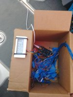
Here is the early prototype that I tested some time ago. Hopefully I can mount it permanently this weekend, but boating takes priority!
 

Attachments

ptwb

Jet Boat Junkie
Messages
148
Reaction score
99
Points
127
Boat Make
Yamaha
Year
2007
Boat Model
AR
Boat Length
23
If you are interested in fuel flow, why not just get some NEMA fuel flow sensors? Of course, adding a chartplotter with nema and the fuel flow sensors is not cheap, so if you're trying to save money, that's great, I understand, good luck and please keep us updated on the progress!

I had decided I was going to be mounting a chartplotter (Lowrance HDS Gen-2 8), so I went with adding the nema fuel flow senders. It is nice knowing the fuel flow, and helps me pick the best speed to optimize fuel, although I have to wonder if it's really paid for itself yet!

I would love to also get temps, rpms, etc but don't like the cost of the analog to nema convertors out there. I see some people experimenting with arduinos and pi for converting analog to nema. Just no time to try it.
 
Top