• Welcome to Jetboaters.net!

    We are delighted you have found your way to the best Jet Boaters Forum on the internet! Please consider Signing Up so that you can enjoy all the features and offers on the forum. We have members with boats from all the major manufacturers including Yamaha, Seadoo, Scarab and Chaparral. We don't email you SPAM, and the site is totally non-commercial. So what's to lose? IT IS FREE!

    Membership allows you to ask questions (no matter how mundane), meet up with other jet boaters, see full images (not just thumbnails), browse the member map and qualifies you for members only discounts offered by vendors who run specials for our members only! (It also gets rid of this banner!)

    free hit counter
  • JetBoaters.Net 2nd Annual SeaDoo Switch Group Buy Sponsored By JetBoatPilot Is Live Now. Save 25% Off Select SeaDoo Switch Gear through October 31st.

    Click Here to go to the Jetboatpilot Seadoo Group buy

    You can delete this notice with the "X" in the upper right>>>

Add a battery kit

mraz72

Jetboaters Commander
Messages
823
Reaction score
310
Points
177
Location
Rochester, NY
Boat Make
Yamaha
Year
2016
Boat Model
242X E-Series
Boat Length
24
I have the Blue Sea add a battery and I am going to get a battery in the next few days. I need to determine which cables I need.

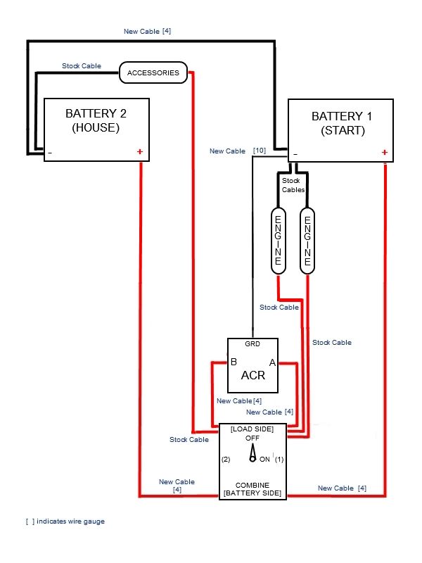
I can use this diagram below
ACR%20loadside%20without%20busses.jpg

I need some help figuring out what cables to buy and what the connectors should be.

For example starting at battery 1 positive, I see the New Cable goes from the positive terminal to the switch, I am guessing that cable has to be the same gauge as the current positive cable on the battery, and I can use Ring connectors on the back of the switch. The I see a cable running from the switch to the A side of the ACR, I guess that's the same gauge and connector types, that all makes sense

But I see a cable from the switch to the engine? Is that the cable that is currently attached to the positive on the start battery?

Another cable I am not sure of is the cable from the switch, to accessories to stock cable on the negative terminal on battery 2, can someone explain that in better detail?

Lastly, I have seen the use of Bus Bars and fuse boxes, should I add them now since I am doing this or get this job out of the way and then add?
 
can someone help on the wire in question? Its the wire going from the negative on battery 2, to accessories (which I don't have), to the battery switch. I don't have any accessories, just adding a battery...
 
The accessories would be anything on the house battery like stereo, amps etc etc. not sure that there should be a ground doing to the switch. Never seen that before.
 
try this diagramACR Wiring.jpg
 
The small numbers in your original diagram indicate wire gauge. For most of the cables, you'll want to use at least 4AWG. I recommend upping that to 2AWG or better if you plan to add amps. You'll have a stock cable from the engine and one for the electronics already connected to your stock setup. You can move those ove to your new switch. The "accessories" spot in the diagram is things like your bilge pump, blower, radio, etc... They all are connected back to the negative to complete the circuit. There will be a stock cable already.

The diagram subysti posted is another good illustration.
 
I used the existing wire (i think 4 awg). I wasnt adding a lot of accessories (just a small amp to power 4 polk db651s), so i used the existing red/black wire from the accessories and wired to the switch. Then i used 4 awg cables i made at West Marine to go from the switch to the house battery. (same of start battery as well...4 awg)...
 
You'll need a negative cable going to the fuse block as well. Same size as the positive. In the picture, the bolt on the top is where the negative cable connects, and the bolt on the bottom is where the positive connects. The three screws at the top on the right are the negative terminals, and the three at the bottom are the positive terminals for the loads you hook up.
 
alright, I am ordering the fuse block and the bus bar. Now i need to determine the cables sizes and getting them made ugh.

I see a 150amp fuse from the battery switch to the fuse block, and that is inline with 2-awg cable. How can I get that fuse inline? I see inline fuses online, but it looks like they are expecting much smaller cable? Here is an example

https://www.amazon.com/InstallGear-...8&qid=1465835244&sr=8-2&keywords=150+amp+fuse
 
I just ordered that one bill, I like that idea better.

Did you guys bolt/screw all of these items into a board of some kind, and then mount the board? I know I can just screw all the items directly on the boat, just curious.

Today I plan on going to my boat with string, pseudo wiring the settup and getting an idea of the length of wires. I will order or create the wires (west marine) going a bit over what I estimate...
 
My switches, fuse panel, breaker, etc... are bolted to the wall shared with the engine compartment. It is a piece of plywood covered in carpet on my boat. This is an old picture, but it shows where the switches are mounted.

battryswitches2.jpg
 
that looks good, probably the way I will go. I would also like a charger, have to figure out which will work. I'm going to go with ChargerGuy.

I'll update this thread with my project pics and results....
 
My switches, fuse panel, breaker, etc... are bolted to the wall shared with the engine compartment. It is a piece of plywood covered in carpet on my boat. This is an old picture, but it shows where the switches are mounted.

View attachment 39163

How is your battery charger mounted? I dont see any screws...
 
Glad I wasn't the only one who saw that. I have a spacer and protector for my charger to keep it away from carpet for safety. I'd recommend it a cheap plastic cutting board and some spacers from a local hardware store. It keeps heat down as they get hot at times.
 
Velcro strip on the hull. The original owner of my boat installed it this way. He removed the carpet and stuck the velcro to the fiberglass. It's been there for over 5 years. I have checked it while it was charging and it wasn't hot enough to make me worry. I do always leave the seat removed while it's plugged in to help vent.

battrycharger2.jpg
 
Ok, now I am working off of the second diagram in this thread. I ordered everything I'll need except cable, here is what I think I need for cable, can someone double check my work? I am going to go with 2 AWG (except where 6 AWG and 16 AWG are depicted in the diagram. I do want to add 1 maybe 2 amps and a subwoofer, do I need to go to 1 AWG wire?

Start Battery NEG -> Bus Bar (36" 2 AWG both ends round connectors)
Start battery POS -> Switch (same wire as above, same size)
Start battery POS -> ACR (25") (pic above says 6 awg, is that a good size?)
ACR -> Bus Bar (12") (16awg with 10amp inline fuse, again, is that a good size?)
House Battery POS -> ACR (30") (6 awg, is this good?)
House battery POS -> Switch (30" 2 AWG)
House battery NEG -> Bus Bar (1.5' 2AWG)

House battery -> ACR (16 AWG for LED, I believe this is optional. Any opinion in this?

for the 2 AWG cables, I want the round connectors, what is the size of those connectors? If I get them made at West Marine, will they know the size if I bring in the bits?
 
I'm looking to pick up the wires for the install, I just want to ensure the above gauges are correct?

If I plan on 2 amps, do I need larger than 2 awg wire to the battery based on the diagram above? I am going to build my own cables, it gets expensive buying pre-made wires, and with a do it yourself kit, I can continue to make wires in the future...
 
Back
Top