• Welcome to Jetboaters.net!

    We are delighted you have found your way to the best Jet Boaters Forum on the internet! Please consider Signing Up so that you can enjoy all the features and offers on the forum. We have members with boats from all the major manufacturers including Yamaha, Seadoo, Scarab and Chaparral. We don't email you SPAM, and the site is totally non-commercial. So what's to lose? IT IS FREE!

    Membership allows you to ask questions (no matter how mundane), meet up with other jet boaters, see full images (not just thumbnails), browse the member map and qualifies you for members only discounts offered by vendors who run specials for our members only! (It also gets rid of this banner!)

    free hit counter

XR1800 4-Stroke MR1 Swap

Quick question: did you feed the stock key switches from the dedicated 3A fused red wire that goes to the Remote control/security module or from the Red wire hanging off the starter relay that pulls from the 20A fuse that is paired with Brown wire to engage the starter ?

If I pull from the 3A I reduce the load slightly on the 20A and I have a discrete line to the keyswitch that powers the Tach's and Yellow wire to light the ECU and fuel sender depending on Port or Stbd as the AR210 is not symmetrical WRT the key/ power switches (this is the way its done in the AR210 with that little slow blow inline BUSS fuse that always corroded)
 
i have to run a yellow wire from each key switch back to the respective ECU to light the ECU and main relay and dress off the wires however engines and boat are one... the AR210 has the yellow wire in the Key switch harness but not in the boat harness as the CDI's were powered from the battery directly through a inline fuse.

engines and boat are one
 
Last edited:
Quick question: did you feed the stock key switches from the dedicated 3A fused red wire that goes to the Remote control/security module or from the Red wire hanging off the starter relay that pulls from the 20A fuse that is paired with Brown wire to engage the starter ?

If I pull from the 3A I reduce the load slightly on the 20A and I have a discrete line to the keyswitch that powers the Tach's and Yellow wire to light the ECU and fuel sender depending on Port or Stbd as the AR210 is not symmetrical WRT the key/ power switches (this is the way its done in the AR210 with that little slow blow inline BUSS fuse that always corroded)
I didn’t modify how my key switches were fed. Only thing I modified under the dash was I tapped the purple wire from each key switch (hot when key is on) and ran a wire back to each respective engine. I connected the new wire to the existing yellow wire that used to sit in pin #15 of the remote security box. I didn’t run anything additional to the ECU itself (except when I was experimenting with trying to get the ECU to illuminate the three warning lights in the tach).
 
I didn’t modify how my key switches were fed. Only thing I modified under the dash was I tapped the purple wire from each key switch (hot when key is on) and ran a wire back to each respective engine. I connected the new wire to the existing yellow wire that used to sit in pin #15 of the remote security box. I didn’t run anything additional to the ECU itself (except when I was experimenting with trying to get the ECU to illuminate the three warning lights in the tach).
:thumbsup:
 
Just remember that there are two yellow wires that go to the remote security box connector. If you happened to remove the connector for the remote security box, and your not sure which yellow wire needs switched power, just apply 12v to each of the yellow wires, one at a time. Whichever one causes the fuel pump to kick on for a few seconds is the one that activates the main relay circuit, and is the one that needs the switched power.
 
Found the problem why the starboard engine was hanging. Apparently I forgot to remove this little rubber piece, and it got jammed up holding the throttle open ever so slightly.
 

Attachments

  • ACAFC00A-3300-4357-95EB-D5C521CFED90.jpeg
    ACAFC00A-3300-4357-95EB-D5C521CFED90.jpeg
    1.6 MB · Views: 7
yeah they show the diode circuit in the schematic... I mocked it all up with test leads yesterday and its all good... i was digging out my weatherpack tools to clean up a couple of corroded pins and wires in the boat harness before I dress everything off. I'll end up with 2 spare 3A circuits in each engine harness one that its battery switched (remote control/security) and one that is ignition on switched (bilge pump)...
 
Found the problem why the starboard engine was hanging. Apparently I forgot to remove this little rubber piece, and it got jammed up holding the throttle open ever so slightly.
good catch... they weren't on the replacement throttle cables that got for a 2006 AR230 HO
 
Speaking of throttle cables, do your throttle levers now only move about half way before the engines are WOT? That's how mine are. I'm afraid that another driver (my wife) may inadvertently try and force the levers to go all the way forward since the levers now only use about half the throw.
 
well i'll let you know tonight after I hook them up.. I ran out of daylight yesterday... IIRC the throttle quadrant has different holes on the lever arms so I presume i can adjust the travel by moving the connection closer to the pivot point
 
Ok, so my next phase in this project is trying to figure out how I can utilize the No Wake Mode functionality. Do I really need it? Not really, but it would be nice to somewhat bring my 20th century boat a little bit more into the 21st century.

My understanding of the boat's no wake mode is that there are two wires in the boat's no-wake switch. When the no-wake switch is "off" the wires are connected together, with essentially no resistance in the circuit. When the no-wake switch is on, the current then passes through a 4.7k Ohm resistor. The ECU sees this resistance in the circuit, and knows that means to activate the no-wake function. The circuit either has no resistance, or some resistance, but the circuit is never open (infinite resistance). The circuit is always closed, and varying the resistance in the circuit tells the ECU whether or not it needs to be in Low Wake mode or not. An open circuit indicates a problem to the ECU.

I suspect that the no-wake mode in the skis probably operates in the same fashion. There is a blue wire coming from the remote security box that goes directly to the ECU. In bypassing the security box, that blue wire must be grounded, otherwise I could not get the engine to start. So once again, no resistance tells the ECU that things are ok, and infinite resistance (open circuit) tells the ECU that there's a problem. I suspect that if I introduced the correct amount of resistance between the blue wire and ground, I bet I could get the No Wake function to activate. The problem is, I don't know what resistance the ECU is looking for.

In an attempt try and figure out what the resistance might be, I dissected my security box since I no longer need it. I am not an electrical guru by any stretch of the imagination, but I decided to take this thing apart to try and see if I could find any clues. The security box was filled full of this rubberized material with small rocks in it. I dug out as much as I could with a screw driver, in hopes that I would find a resister. Unfortunately, I did not find a resistor, but I did find a varistor, which as I understand it, varies its resistance as voltage changes. Ok, that doesn't really tell me much, so it looks like I'm going to try trial and error to figure out what resistance the ECU needs in order for Low Wake Mode to activate. I have a 10k Ohm potentiometer, which basically allows me to vary the resistance using a dial. The idea is that I will start the motor with no resistance on the pot, then as motor is running, slowly increase the resistance while monitoring YDS to see if I can get Low Wake Mode to activate.

Fingers crossed...
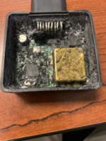
8A502001-E6BC-4CFC-9D96-A8C93D0FDA8A.jpeg
 
Last edited:
i will double check for you but IIRC My port harness is the same as your harnesses and throws no code... My starboard harness is as described in the FX HO wiring diagram, I have the blue wire grounded and I get a code... it doesn't hurt anything I just cant clear it using the 6B6 ski ecus... I didnt check this with the 6P6 boat ecu's in the starboard ski harness.
 
i will double check for you but IIRC My port harness is the same as your harnesses and throws no code... My starboard harness is as described in the FX HO wiring diagram, I have the blue wire grounded and I get a code... it doesn't hurt anything I just cant clear it using the 6B6 ski ecus... I didnt check this with the 6P6 boat ecu's in the starboard ski harness.
Which code is being thrown on your starboard harness?
 
Which code is being thrown on your starboard harness?
i'll check tonight it may be the steering sensor I can t remember...
 
Speaking of throttle cables, do your throttle levers now only move about half way before the engines are WOT? That's how mine are. I'm afraid that another driver (my wife) may inadvertently try and force the levers to go all the way forward since the levers now only use about half the throw.
nope throttle cables are within an eighth of what they were... had to make some extenders at the throttle body to get them to adjust properly... posted details in my thread
 
No luck with varying the resistance between the blue wire and ground wire. I ran the engine on the hose and slowly varied the resistance using the potentiometer, while monitoring things with YDS. What’s more, is that this time I was able to crank up the motor with the blue wire completely discounted from ground. Previously, the motor would not fire if the blue wire wasn’t grounded. A bit confused by the results.
 
Left work a little early today and took my kids and a buddy of mine on a quick jaunt down the Tennessee River into downtown Chattanooga. My kiddos visit the Tennessee Aquarium quite a bit, and to them it was neat seeing it from the river. It’s the building at the end of the video with the triangular glass roofs.

AE6F98E5-AC15-43CE-A2C3-25AB518C1D81.jpeg26553620-A9A7-45AE-A81A-B4835F01C25F.jpeg
 
Last edited:
In other news, the boat maxed out at 50mph on the GPS. I think the jet pumps need some attention. I’ve never messed with the XR’s jet pumps, nor on the Exciter 220 that I used to have. I’m sure the stock impeller isn’t helping either.
 
im calling my conversion done... I have 2 hours on the engines and no codes... the skip in the stbd engine appears to have been a bad plug/weak coil... Im down to regular maintenance Items now... I was able to get 32MPH at 5000 RPM with just a little down tab...
 
im calling my conversion done... I have 2 hours on the engines and no codes... the skip in the stbd engine appears to have been a bad plug/weak coil... Im down to regular maintenance Items now... I was able to get 32MPH at 5000 RPM with just a little down tab...

Nice, I'm curious how fast your boat will top out. Will likely need to re-pitch your Solas impellers?

I've been enjoying the boat on the weekends with my kiddos, looking forward to Memorial Day coming up.

On my previous runs I had left out the engine tray insert so that I could quickly access things in the engine bay on the fly while out on the water. Last weekend I attempted to install the engine tray in order to cut down on noise, and realized that the tray conflicts with the airboxes of the MR1s. I guess the motors are too tall for the tray to sit down all the way. Tray sticks up a few inches. I am still able to close the engine hatch however.
 
Back
Top