• Welcome to Jetboaters.net!

    We are delighted you have found your way to the best Jet Boaters Forum on the internet! Please consider Signing Up so that you can enjoy all the features and offers on the forum. We have members with boats from all the major manufacturers including Yamaha, Seadoo, Scarab and Chaparral. We don't email you SPAM, and the site is totally non-commercial. So what's to lose? IT IS FREE!

    Membership allows you to ask questions (no matter how mundane), meet up with other jet boaters, see full images (not just thumbnails), browse the member map and qualifies you for members only discounts offered by vendors who run specials for our members only! (It also gets rid of this banner!)

    free hit counter
  • Announcing the 2024 Jetboat Pilot 10th Annual Marine Mat Group Buy for JetBoaters.net members only! This is your best time to buy Marine Mat from JetboatPilot - you won't get a better price - 30% Off! Use Coupon Code JETBOATERS.NET at checkout.

    So if you are tired of stepping on really hot snaps/carpet, or tired of that musty carpet smell - Marine Mat is the best alternative out there! Get in on this now, or pay more later!

    You only have until September 30th to get in on this.....So Hurry!

    You can dismiss this notice by clicking on the "X" in the upper right corner>>>>>>>>

3D Printed Jet Boat

3D_Print_'em

Member
Messages
1
Reaction score
1
Points
10
Boat Make
Other
Year
2024
Boat Model
Other
Boat Length
Other
Hi all,

I have been looking for feedback on multiple forums and came across this one and need some more feedback or suggestions for my 3D printed jet boat.
I am making and designing a scaled down electric jet boat for a school project and am focusing on the engineering and development of the propulsions systems. This involves the intake which directs water towards the impeller and is then driven to the end of the jet where the velocity of the water builds. I just need to know if the design I have made would work for this scale boat and what concepts I have to keep in mind while designing the rest of the Jet pump.
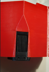
Here is a photo of the intake:
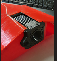
1727145125230.png1727145145002.png
The impeller I have designed is driven directly by a brushless motor and is coupled to a shaft which spins the 3D printed impeller. After seeing how others design an impeller, I made the diameter of the shaft increase towards the end of the jet pump to allow the blade pitch to increase and drive the water out faster. Here is my design of the impeller: It is a two-stage impeller in order to reduce the cavitation of the water around the impeller.
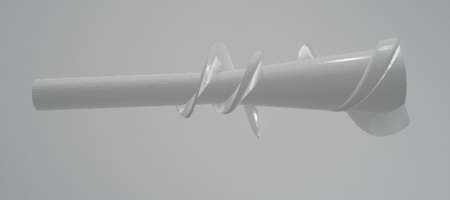
1727145314101.png
Any feedback or suggestions are greatly appreciated,
Thanks
 
Looking at what you've got there, if you are doing some testing, I would try fewer bars on the intake grate, maybe 3 if possible. Smoothing of everything will give you better flow as well, not sure the effects on a micro scale like that, but small changes can make a HUGE difference in our boats, so I can see it helping. I've seen acetone used for smoothing out a finished 3D printed product. If you can't access it due to size, if you can spray it in there and work with some Q-tips, that may work for this. Great Stuff expanding foam cleaner is sprayable acetone in a convenient form factor, and I think you can add a straw to the nozzle tip.

Looks interesting, would be cool to follow your project and see the final result as well!
 
@3D_Print_'em Looks like a cool project.

@drewkaree is spot on with smoothing out that transition on the intake. You want as few sharp corners and as few drastic changes in shape as possible. Smooth lines that allow the water to adhere to the surface of the intake tunnel without disturbance to flow as much as possible. Have a look at your fluid dynamics books to see how sharp corners affect localized pressures as compared to sweeping bends. Less pressure drop ahead of the impeller is best. Same goes for the intake grate. You want to keep the "big" stuff out, but the little stuff will likely flow through just fine. I would at least half that grate count (double the spacing between).

You're on the right track for developing pressure, however you're doing it at the wrong spot. The impeller doesn't develop the pressure differential, the nozzle does. The impeller just generates flow against the restriction of the nozzle. The impeller you have drawn there would be great if you needed to pressurize something very viscous like molten plastic, or peanut butter, but water will just flow around it and not pressurize as you think it will. Have a look at a "double pitched" impeller with a single diameter inner shaft. The Yamaha 6CW is designed like this and has been found to be quite versatile across many boats. I would start with that general design, and tweak as needed to develop flow.

The nozzle is where the magic happens for propulsion. You have a constant mass system with a change in velocity across the nozzle. This generates a change in momentum, which in turn generates the force to motivate the boat forward (at least at any speed). The thought experiment I use is to consider standing in a john boat. Now throw an cinder block off the back, which way does the boat move? Is it because the block pushed against the air? Is it because the block was under pressure? It's because you changed the momentum of the block and the resulting opposing force moved the boat forward. Nozzle does the same thing, just with millions of tiny water molecules instead of cinderblocks. Look into the size reduction ratios on existing nozzles and scale down from there. I think our 155mm pumps reduce down to like 75mm outlets. Just over a 4.2:1 reduction in area, so the existing water should be going roughly 4 times as fast as it came in. That will generate the force needed to move the boat forward.

Good luck and keep us posted on what you learn. Lot of engineering topics covered in what is otherwise a very simplistic driveline.
 
Back
Top