• Welcome to Jetboaters.net!

    We are delighted you have found your way to the best Jet Boaters Forum on the internet! Please consider Signing Up so that you can enjoy all the features and offers on the forum. We have members with boats from all the major manufacturers including Yamaha, Seadoo, Scarab and Chaparral. We don't email you SPAM, and the site is totally non-commercial. So what's to lose? IT IS FREE!

    Membership allows you to ask questions (no matter how mundane), meet up with other jet boaters, see full images (not just thumbnails), browse the member map and qualifies you for members only discounts offered by vendors who run specials for our members only! (It also gets rid of this banner!)

    free hit counter

AR195 DVSR Separating House and Start Battery

BudMC77

Member
Messages
2
Reaction score
0
Points
10
Boat Make
Yamaha
Year
2024
Boat Model
AR
Boat Length
19
First time posting, long time reader.

Have a 2024 AR195 that I'm attempting to add a BEP 716 cluster with the DVSR. My goal is to completely isolate the house battery and the start battery. Or at least, have the radio/USB socket/accessories on the house battery while leaving engine operations on the start battery. Is this feasible considering the 195 was built for single battery? I have the service manual and it doesnt include a boat wiring diagram, only the engine harness wiring. I found the 195S service manual and it does in fact include the diagram but unfortunately the 195 is wired a little differently. Such as having a separate fuse for the radio and USB.
Any reason why the diagram would be omitted from the service manual? Anywhere else to find the diagram.

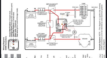
I would imagine the only option would be to run new power wires for accessories that would be on house battery. Which existing factory wires would be wired to the switches? Attached are BEPs diagrams on wiring the switches.

Thanks in advance.
 

Attachments

  • Screenshot_20250827_222021_Chrome.jpg
    Screenshot_20250827_222021_Chrome.jpg
    557.8 KB · Views: 6
  • Screenshot_20250825_203708_Chrome.jpg
    Screenshot_20250825_203708_Chrome.jpg
    380.2 KB · Views: 7
Thats really quite strange that there are no electrical diagrams in the service manual… do you have the paper version or the digital version? If nothing else, and you can visit a dealer go and ask to see their shop manuals.

It seems like with a little bit of investigation you could move most of the house loads off to a dedicated house battery thereby transferring the bulk of the house usage away from the start battery. Can you break out the accessory wiring from where it attaches to the battery now?

Good choice on going with the BEP switch! They are super compact and simple.
 
I found it quite strange as well. First time ive seen such a thing. I do have the digital version of the service manual but I couldn't imagine they would leave that one diagram out. Thought it was a downloading issue but it doesnt seem to be so.
I didn't think to visit the local-ish dealer. That may be my only option in regards to a diagram. If I had the diagram, I could verify which house loads are in the accessory wiring. From what I can tell, it doesnt really have any dedicated accessory wires. The factory had 4 wires on the factory ON/OFF switch. A "+battery switched" wire and "main" (which goes to the starting solenoid) wire going on the load side of the switch. Then a "C" wire and the "auto bilge" going to the line side of the switch. I experimented with the "main" on the new start switch and the "+battery switched" wire on the new house switch. Engine will run with only the start switch on but no connext/radio. Leaving me to believe everything but the ecm is on the "+battery switched" wire. Connext did come back on once house switch was on.

Currently, I am adding an auxiliary fuse box that will be under the helm. Running 8 awg wire from the house switch to a 30A breaker then up under the dash. The plan is to pull power from the aux fuse box for the radio, USBs, and any other future low draw circuits. I think this may be the best course of action just help keep frustration and factory harness intact.

As far as the factory harness battery connections that currently run the connext, ECM, and other critical components that originally connected to the ON/OFF switch, to the Start switch. This way critical components are all on the same battery and should help with keeping voltage fluctuations to a minimum.

Also did the DVSR mod where connecting the small red trigger wire to the load side of the start switch. When the boat is on the water, switch is on, engaging the DVSR to do its job. Then when off the water, switch is off, and batteries are isolated. Allowing for individual battery chargers to charge at home. At least to my understanding this is this should work.

Adding an amplifier for the stock speakers as well in which will run off a 60A breaker feed from the house switch.
This should isolated all of the stereo system and USB chargers to the house circuit. The only thing that should be drawing from the start battery while floating is the connext in float mode. Im assuming transducer and such will also be drawing from the start battery. Not sure if it will be worth while to try to isolate these circuits to the house battery or not. Shouldn't be an issue unless you were floating for like two days. Would need to test the amp draw on start battery while in float mode to be certain.

@FSH 210 Sport what's your thoughts on this plan?
 

Attachments

  • 20250903_192148.jpg
    20250903_192148.jpg
    1 MB · Views: 2
  • 20250903_192144.jpg
    20250903_192144.jpg
    871.2 KB · Views: 2
Back
Top