• Welcome to Jetboaters.net!

    We are delighted you have found your way to the best Jet Boaters Forum on the internet! Please consider Signing Up so that you can enjoy all the features and offers on the forum. We have members with boats from all the major manufacturers including Yamaha, Seadoo, Scarab and Chaparral. We don't email you SPAM, and the site is totally non-commercial. So what's to lose? IT IS FREE!

    Membership allows you to ask questions (no matter how mundane), meet up with other jet boaters, see full images (not just thumbnails), browse the member map and qualifies you for members only discounts offered by vendors who run specials for our members only! (It also gets rid of this banner!)

    free hit counter

DVSR help...

Good stuff gentlemen. Too bad the BEP crossover voltage isn't programmable. Even an AGM house at 12.8v volts would risk cooking an FLA start a little bit since that is also the BEP cut out voltage for the bridge.
 
Good stuff gentlemen. Too bad the BEP crossover voltage isn't programmable. Even an AGM house at 12.8v volts would risk cooking an FLA start a little bit since that is also the BEP cut out voltage for the bridge.
I wouldn’t worry about that with an agm battery… the voltage cut out of the dvsr is 12.8 v I think I said 12.7 above, so it would not take much for the voltage to drop to the cutoff and the pick up voltage is 13.4v.. so its totally fine with any lead acid battery set up.
 
Well that's good to know. AGMs would be a nice replacement for my FLAs some day.
 
Well that's good to know. AGMs would be a nice replacement for my FLAs some day.
Agms don’t have the equivalent storage capacity as Fla batteries…. Save your money and buy the Fla batteries. Your best bet is an Interstate Fla battery….or a Sam’s or Costco one, that’s the best bang for the buck.
 
I think that you have to purchase the service manuals and they’re not cheap - I don’t have one. :-/
About $100. I do have it and it's okay, but not great. The wiring diagrams are very valuable.
 
I did this mod on Saturday and it works great. I intercepted the blue wire to the fuel pump in the engine compartment. The harness goes to the top of the engine at the fuel rail. I did not cut the blue wire but stripped 1/2” of insulation and soldered a 22 gauge wire to it. I sealed it with liquid electric tape. At the Dvsr splice I used one of those self soldering, self sealing connectors that you use a heat gun on to seal. Either way works but I did not have to juggle around the open floor hatch. Thanks for your detailed write up!
Do you have any pictures of what yo spliced and your set up Im looking to do this next week and this seems to be the most relatable one so far. Thanks in advance
 
@WiskyDan did a great job of hooking up the run hot configuration on his boat, go to page 8 and post 143 in this thread.
 
@WiskyDan did a great job of hooking up the run hot configuration on his boat, go to page 8 and post 143 in this thread.
So I read through that all that I was looking to see where the blue wire was in the engine compartment vs puling up the floor board thats all. Others I see what to do but was trying to shorten that run. Everything else make sense, I will try that way first but from searching around I was told to remove the DVSR completely and connect that same blue hot wire to my DC to DC converter D+ in. FSH 210 Sport I have read a lot of your post and you seem very knowledgeable so maybe you can help me a bit more? So this is what I just bought. My plan is to replace the house battery with this 320ah lithium. I beach a lot and play music quite a bit and have a SDX6 wet sounds amp almost maxed out with 6 tower speakers. I was draining my house battery so I either had to move and drive for a bit or turn it off. Im removing my 10amp NOCO 10x2 for now because it’s also bulky. I know the battery fits so my next step is to start connecting things together.. just one problem I dont know where to start disconnecting and connecting. Ive already removed the plates off the back and see the red loop but im not sure if I just remove it completely or splice into the hot with what im trying to accomplish. Thanks in advance.
 

Attachments

  • tempImage7dTdPP.png
    tempImage7dTdPP.png
    21.6 MB · Views: 23
  • tempImageJLuYgI.png
    tempImageJLuYgI.png
    16.6 MB · Views: 22
  • tempImage8xv89e.png
    tempImage8xv89e.png
    12.4 MB · Views: 22
NO Do not remove your dvsr and connect your blue wire? To the dc to dc charger. That is very bad advice.

You probably cannot use that dc to dc charger because the alternators on your boat do not put out enough power to run it, and you do not need it in the first place.

The whole point is to hook up your dvsr to a fuel pump hot so it activates when the engines are running and shuts off when the engines are off. Because you cannot leave a lfp battery connected to a lead acid battery with the engines off.

You are going to need that NOCO charger to charge the start and house battery. Again your engines don’t make enough power to charge your batteries. I would suggest a Victron IP 67 25A charger for your lfp battery, the 10A will work but it will take 32 hours to charge that 320Ah lfp battery if you discharge it 100%. And perhaps a 10A charger for the start battery.

Get the AC connector from NOCO and that makes it easy to connect your extension cord.

If you look at my battery upgrade thread linked in my signature there’s probably a diagram for the dvsr that will show you how to modify the red wire for storage or run hot mode.

Is that a smart shunt in the box? Or does it just connect to that monitor thingie ?

Hope that helped you. If you have questions ask !
Okay, allow me to explain why I was told to remove the dvsr was because of the uncontrolled surges, charging instability, and possible damage to charging system. I know the lithium will draw a lot and the dvsr cant regulate that from what I understood. So that was the reason I was told to go the route mentioned in the previous comment. I also read somewhere else that it doesnt produce a surplus of power so what you stated about it not putting out enough power to run does makes sense so you can see where my confusion is coming from. It mentioned it would have to be above 7000rpms to be charging and realistically im not maxing out my speed for that long to probably get any real charge.

So now in theory hooking up that fuel pump hot wire to the dvsr will allow me to hook everything to the lithium battery as it was with the lead battery and still play music while beached and have no issues or any other modifications?

I also had no problem understanding how to hook up to a fuel pump It just seemed like there was that same wire closer to the dvsr in the engine compartment. I was looking for that picture.

I might just make those an SAE connector and charge after the day out because I dont really have a lot of space especially if use the Victron tied in there. I thought about the AC port originally but didnt want to cut into my boat.

It is a LiTime 500a battery monitor with a smart shunt 8v -120v. I really do appreciate the help and time to explain this all. Ive tried to do more research but I really cant find much more.

 
If you use the sites search engine you will find a lot of information on the dvsr subject, most of it good and a small part misinformed. The only thing worse than no information is bad information and who ever told you those things has given you bad information.

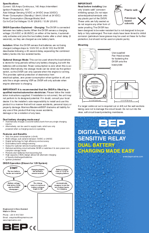
In post 43 in the thread linked shows a screen shot of the BEP marine instructions / description of how the DVSR operates.

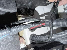
The DVSR is an automatic charge relay, it doesn’t produce any charge current, regulate charge current or voltage, that is the realm of the voltage rectifier / regulator. The reg / rect converts the three phase AC voltage to DC voltage and the regulator shunts unwanted voltage / current to ground. The DVSR isolates / opens connection between the start and house battery when the voltage drops to 12.8, and closes when the voltage is 13.4 paralleling the start and house batteries =when the engines are running and the alternators are charging. The resting voltage of a LFP battery is 13.4 volts when fully charged and doesn’t drop to 12.8 volts until it’s almost fully discharged, this is why the DVSR must be wired in the ignition mode or manually switched mode of functionality, otherwise the DVSR will stay closed and the LFP battery will discharge into the lower voltage lead acid start battery-that’s simple electrical theory-.

The alternators on our boats produce roughly 14 amps above 3500 rpm and about half that at idle. So 28 amps when you’re cruising, well below the 125 amp continuous rating of the BEP marine DVSR.

Read post #20 in this thread.

Our permanent magnet alternators (PMA) and their regulator / rectifiers are a great marriage with LFP batteries and their inherent low resistance due to the fact that the PMA are always at full output or 100% duty cycle. LFP batteries can be a problem for variable magnet alternators (VMA) found in automotive style alternators, very few of these systems can operate at a 100% duty cycle without catastrophic damage, that’s where a DC to DC charger comes in, to limit the charge going into a LFP battery and that reduces the duty cycle on the VMA. For example, if the VMA is 100A and one is using a 35A DC to DC charger that reduces the duty cycle to 35% on the VMA. Typically a DC to DC charger requires 35 amps of alternator output to operate and as explained above the alternators in our boats are no where near that,

Cutting a hole in your boat for the AC charger connection is not a big deal, and having the on board charger makes charging the batteries very convenient, but you do have to leave the compartment hatch open some for air circulation to let the heat out. If you’d rather use a portable charger that’s up to you, just be sure and use the correct charge profile for each battery chemistry.

I like the Victron chargers with their Bluetooth connectivity so I can see what’s going with the charger during the charging process, and after it’s done I can see how the charge cycle went. I have the 25A / 10A model, this gives me the ability to lower the charge rate if I’m charging some place that doesn’t have the capacity to charge at the higher rate, that’s happened a couple of times when I’ve been at marinas or campgrounds.

Having the shunt will enable you to see just how many KWh / Ah you have used while you’re out on the water. If you’d rather use land the negative lead of the battery charger to the system ground side of the shunt you’ll be able to see the amount of KWh / Ah the battery charger put into the battery. Also when you’re on the water and run the engines you’ll see the current flow from the alternators into the house battery. On my boat the most charge current I’ve seen going into the LFP battery is 26A for a short time then it slowly decreased to 17 A, this was after I purposely discharged the house battery to 50%.
 
Okay, allow me to explain why I was told to remove the dvsr was because of the uncontrolled surges, charging instability, and possible damage to charging system. I know the lithium will draw a lot and the dvsr cant regulate that from what I understood. So that was the reason I was told to go the route mentioned in the previous comment. I also read somewhere else that it doesnt produce a surplus of power so what you stated about it not putting out enough power to run does makes sense so you can see where my confusion is coming from. It mentioned it would have to be above 7000rpms to be charging and realistically im not maxing out my speed for that long to probably get any real charge.
Most of this is false information you were given. The DVSR does not regulate the voltage, all it does is create a bridge to charge the batteries when the voltage goes over a certain amount.
It doesn't cause an "uncontrolled surge" , no surge at all. Just a bridge for the 2 banks thats all.
There isn't any charging instability as well.
And no you dont need to go to 7k rpms to get charging voltage. If that was the case most batteries would be drained by going 30mph

As soon as the engine fires the voltage at the battery is aprox 14volts and thats at idle
 
Hello all a little update and Im pretty certain I did everything correct. I made it look as clean as I could. I have done the DVSR mod and connected to the fuel hot wire in the engine compartment. After researching a little more seems like I could have just connected the red loop to the start terminal in the cluster it self and save my self the run. I do have to connect my noco charger still which is where I may need some help unless it’s just as simple as connecting them to the terminals and pushing lithium on one and lead on the other when charging. If there are any concerns please comment and let me know. Also read something about the red light so if someone could explain when that is supposed to be on and suppose to be off. ( on when charging off when its met its voltage?) I could be wrong about that just a guess from what it thought I read. Thanks and hoping this will help others as I was confused just a bit when reading the forums. I have a 2023 222 XD IMG_3812.jpegTest Fit IMG_3864.jpegRed loop on the DVSR clusterIMG_3863.jpegFuel line HOT wireIMG_3865.jpegCut and Solder IMG_3872.jpegHeat shrink non using end to protect wire. IMG_3862.jpegFuel hot wire came out of center hole and followed to engine compartment to find blue wireIMG_3867.jpegRan wire into cut out and placed into new wire loom that went back to fuel linetempImageT3SlzZ.pngZip tied the new wire loom and connected to the blue wire with a T Tap and then electrical tape to protect it all. IMG_3931.jpg Final… I had to run a new bus bar for the monitor. My only problem I ran into is I was short by a foot with the 4 gauge wire I ran to my amp which is the only reason for the upgrade to the lithium battery and this project. So far everything turns on but would like to get in on the water and just make sure. @FSH 210 Sport
 

Attachments

  • tempImageqlXwPh.png
    tempImageqlXwPh.png
    14.6 MB · Views: 9
Last edited:
but you do have to leave the compartment hatch open some for air circulation to let the heat out.
Are you saying the compartment with the battery needs to be left open, or the compartment with the charger?
 
I did the red wire mod and just connected it to the output side of the start battery switch.
 
Are you saying the compartment with the battery needs to be left open, or the compartment with the charger?
Where the charger is, to allow the heat from the charger to escape. If the batteries are flooded lead acid then that compartment should also be left open to allow the gasses to escape.
 
Last edited:
Hello all a little update and Im pretty certain I did everything correct. I made it look as clean as I could. I have done the DVSR mod and connected to the fuel hot wire in the engine compartment. After researching a little more seems like I could have just connected the red loop to the start terminal in the cluster it self and save my self the run. I do have to connect my noco charger still which is where I may need some help unless it’s just as simple as connecting them to the terminals and pushing lithium on one and lead on the other when charging. If there are any concerns please comment and let me know. Also read something about the red light so if someone could explain when that is supposed to be on and suppose to be off. ( on when charging off when its met its voltage?) I could be wrong about that just a guess from what it thought I read. Thanks and hoping this will help others as I was confused just a bit when reading the forums. I have a 2023 222 XD View attachment 243491Test Fit View attachment 243492Red loop on the DVSR clusterView attachment 243493Fuel line HOT wireView attachment 243494Cut and Solder View attachment 243495Heat shrink non using end to protect wire. View attachment 243496Fuel hot wire came out of center hole and followed to engine compartment to find blue wireView attachment 243497Ran wire into cut out and placed into new wire loom that went back to fuel lineView attachment 243498Zip tied the new wire loom and connected to the blue wire with a T Tap and then electrical tape to protect it all. View attachment 243500 Final… I had to run a new bus bar for the monitor. My only problem I ran into is I was short by a foot with the 4 gauge wire I ran to my amp which is the only reason for the upgrade to the lithium battery and this project. So far everything turns on but would like to get in on the water and just make sure. @FSH 210 Sport
So sorry I missed this back in February….
The red light on the dvsr module means that the contacts are closed, with the way you’ve connected the dvsr red wire this should only be on while the engine is on that you connected to the fuel pump hot which is exactly what you want with a lead acid start battery and LFP house batteries, DVSR only active while the engines are on.

Otherwise it looks like you’re all set!
 
Last edited:
I just cut the red loop wire as close to the end as I could on the side closest to the red marked post, crimped a 3/8” ring connector on the wire and it was long enough to reach over to connect on the battery master switch post. Took about 10 minutes.
I just did this. I left about an inch of the red wire at the top so I could heat shrink it. I realized 10 minutes after putting the battery switch housing back together that I forgot to heat shrink that loose end. You cut yours so short, I doubt you were able to do anything to secure it. Have you had any issues with it? I'll probably open it back up and heat shrink it, but part of me wants to not bother with it.
 
Back
Top