• Welcome to Jetboaters.net!

    We are delighted you have found your way to the best Jet Boaters Forum on the internet! Please consider Signing Up so that you can enjoy all the features and offers on the forum. We have members with boats from all the major manufacturers including Yamaha, Seadoo, Scarab and Chaparral. We don't email you SPAM, and the site is totally non-commercial. So what's to lose? IT IS FREE!

    Membership allows you to ask questions (no matter how mundane), meet up with other jet boaters, see full images (not just thumbnails), browse the member map and qualifies you for members only discounts offered by vendors who run specials for our members only! (It also gets rid of this banner!)

    free hit counter

2016 240 Ballast Setup Question: Valves?

It not too high but I would not want them mounted there. I was thinking two pumps each side. Keep the twin theme going. It there someplace to mount them in the bilge?
Frankly my only concern was that those would be too high, level-wise, decreasing pump efficiency. But if that is NOT the case, this is going to be my primary target for possible pump placement - I can build little stance/mounts for the pumps deep inside those compartments as those go in and around to sides real deep, I wouldn't even be losing much storage space.
Alternatively I thought about placing two smallish custom bags in there, filling through aux intakes. But that maybe expensive and not very effective, so at the end of the day it will be just one huge bag on the platform or two large ones. I don't think it's avoidable. And with bags there- the storage compartments become kind of useless anyway

--
 
I found the through hull flow chart.
upload_2017-3-9_19-42-22.pngpump 003_s.JPG
I mounted my pumps on a piece of tasteful 3/4" plywood. Made them easier to mount and I would think would also work with a pair of pumps. You could even mount the relays to the board then only have to route the main power wire to the pump location. Cam.
 
I found the through hull flow chart.
upload_2017-3-9_19-47-40.png
I mounted my pump on a tasteful piece of 3/4" plywood which made it easier to mount in tight location. That would work for 2 pumps as well and you could even mount the relay beside the pumps and only run the main power wire to the pump location. Cam.

pump 003_s.JPG
 
Having hard time finding good info -- wondering if the johnson/jabsco pumps would work well mounted in those wet storage compartments (which would place their impellers approx 18" above the water line). I could see myself going down to 3/4" hose if that would help (reducing dead volume). I figure with a system like mine, dedicated intake/ line per bag, I think my fill/drain times would still be fine with 3/4" hose the drop in a system like mine would be more like 20% (and not several fold) from what I can find.
I could still use 1" hose pieces to connect the pump flanges (without needing to use 1/2" male connectors) just like @KXCam22 connected his, above. Those are great pics.

--
 
I think you guys are over thinking the suction thing on the pump.
Pump School:
conclusion: This pump will work in ANY location in the boat with any arrangement of 1" intake hose, as long as the through hull does not restrict the flow rate or you have too many 90deg fittings (like about 50).

The draw on the johnson pump is rated at 8.5 psi max, from the manual while flowing 11.1 USGPM. That is very good. In suction terms, 1 psi=2.31 feet.

When calculating NPSH, there are 2 main component, NPSH = elevation head (height of bags above water) - friction head loss (water friction in the intake pipe). So the 8.5 psi in the manual tells us that the total NPSH of the pump can be 8.5*2.31=19.6 feet. This means that, without intake restriction, you could place the pump 19.6' above the water and have it work. Friction head loss is the water friction in the pipes. Large pipes have less friction and 90 fittings add friction.

For a calculation I am using:
- intake line length of 10', through hull to pump (mine is about 5')
- discharge line length of 10', pump to furthest bag. (mine is about 6')
- approx 0.068' loss per foot of 1" pipe, 30% loss for fittings. (My connections are all straight pipe but my center bag has 2 90 deg fitting is in)

elevation head = 3', bags are approx 3' above water.
line losses = 10' intake + 10' discharge = 20' * .068 = 1.36'
fitting losses = 1.36 *30% = 0.408'
Total Head required is 3'+1.36+.408' = 4.768'

Notice that the pump will put out 19.6' and still flow 11.1 USGPM. I our case 19.6-4.768 = 14.832', so we have almost 15' of excess pump capacity to flow water. Without going into more extreme calculations I would say that you can put the pump anywhere in the boat and still achieve maximum flow rate out of the pump, as long as the intake is not restricted. Based on the throughull intake flow rates, you could probable run two pumps off a single 1" throughhull, as long as you used a straight pipe run and maybe 1 tee, and still get max performance.

Hope this helps. Cam.

edit: Added the ballast pump manual
 

Attachments

Last edited:
One thing I will point out from that install is that having a check valve in the water intake line reduce flow by 10% or more. The only thing it does is allow you to drain your ballast out a vent above waterline so you can hear it stop splashing to know your bags are empty. Also it requires an additional 2 holes in the boat for each bag. I am not a fan of that approach although it does have its one advantage. I had trouble with those insert fittings from wakemakers, the single barb black ones. Mine all leaked. A multi-barb regular one from the sprinkler shop did not. Love his mockup of the intakes, very wise way to do it - I spent a lot of time looking and planning mine before I cut the hole. It also shows the hassle of multi-intakes when combined with multi shutoff valves. The valves are big. I would not have put a tee right after the pump. Kills flow. In this install it would be better to have a direct run flow from pump to bag and tee off for the drain. After all, why sacrifice fill time to have good drain time when you don't really care about drain time. When I drain we are usually headed back to the ramp at high speed. But also, too easy to criticize after the fact. He did a lot of work and his install looks very good. Cam.
 
I'm starting to have some clarity here, LOL. Really excellent pointers, @KXCam22!
Also helped looking at the OEM 242X system which is like most factory ballast systems, inadequate.
I'm pretty much all set to mount the pumps in the stern storage spaces.
Will not use shutoff valves on intakes, just connect 1" fill/drain hose, short run strait up to pump flanges (and then on to the bags), no valves!
I may vent later, but not initially; need to see how it all works.
I will install a single electric shutoff right at the battery to disable the system when not in use, this will prevent accidental activation of pumps by dashboard switches.

--
 
Your plan sounds pretty good. It amazing how, once you start pondering and exploring options, how a good plan starts to come together. The electric shutoff is a good idea since you only really use the ballast system 2x an outing. Keep the vents in mind. I think that they are vital and easy to do. With the flow rate of a 1", and no valve or other fittings to restrict, you could likely share a 1" intake between 2 pumps without slowing fill times. Cam.

PS If you use real ballast hose, ensure that it is smooth in the inside and not ribbed slightly on the inside. The ribbing makes leak proof connections difficult and worse it causes turbulence which reduces flowrate somewhat. Not sure how much but every bit helps.
 
Last edited:
I must say - I have to give it to Yamaha, parts of their ballast system are great!

I finally had a good look at a boat show today, the pics are from a 212X which they had on the floor, but same difference.
What I REALLY like is the ski locker part of the system: super simple. Basically - a Jabsco pump with a two foot 1" hose looping around to the intake valve (through hull), and a direct 1 foot 1" hose to the bag. That's it. No vents. Kind of love it, definitely the way to go for the ski locker ballast.

The only two issues I can think of are:
1. not sure why they use a plastic male connector and a quick connector on the bag side - instead of just going with the 1" hose over the barbed pump inlet - like they do on the intake/drain side
2. the bigger issue is the intake/drain valve that they are using; that locker is same as engine bay - a "pseudo-double hull" insert, so if I wanted to use a simple through hull bronze intake, I would have to devise some kind of (fairly flexible) flange to go over the inside surface (to preserve watertightness of the locker).

upload_2017-3-11_12-56-14.pngupload_2017-3-11_12-56-55.png
upload_2017-3-11_12-57-28.pngupload_2017-3-11_12-57-55.png

If I can figure that out, I would modify my plan, and go with the intake-pump for the locker installed in the locker.
So, I would have very simple system with very short hose runs.
--
 
Actually, I was wrong, the 212X ballast piping IS different. I was confused but glad I by chance looked at the 212X today, never would have thought those were plumbed differently.
So, it is the 212X, not the 242X that has the ballast module that I really like, it is a completely independent circuit for the ski locker (the 242s have it integrated into the one system with rear lockers).
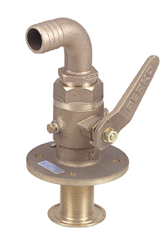
Here is the 212X module, that valve with the flange is #47. I wonder if could just go with the big bronze mushroom intake and bolt it down through the double fiberglass layer, which is what the factory seems to be doing:
upload_2017-3-11_13-11-8.png

The #47 part is something like this, basically:
Perko-Bronze-assemby-Thru-hull-seacock-90-tailpiece.jpg
 
Last edited:
You cant see it in my pics but on my through hull I have a large FRP (fiberglass) washer on the inside of the hull (1/2" smaller diam than the bronze one in your pic) to spread out the clamping pressure. You could build something similar. Hose length is not too much of an issue (on fill times) unless it is hard to run. On the 230 it is a straight shot from the engine bay, under the tank hatch, and into the ski locker with only 2 holes drilled I recall. A perfect heater hose run. Although plastic, that yamaha throughull looks nice and compact. Just a thought, before you get carried away with fast fill-time thoughts, keep a practical mind on how big of bags you can fit and how big the aux bag on the deck will be. My point is that in general, by the time you have rigged up the aux bag and secured it for filling, the other bags have already been filled, so the aux bag does not really need its own dedicated pump. I have the 2 pumps for 4 bags and for me, having a 3rd or 4th pump would not really increase my total fill time by more than a minute or two, due to the human time it takes to get an 800lb aux bag ready. Easy to get a 5min fill time but could cost 2X more to get a 3 min fill time. On my aux bag I have the SUMO quick link fitting, and a matching one on my umbilical hose. I had to upsize the OEM oring on the fitting to keep it from leaking when filling. Cam.
 
For the wiring challenged here is a complete wiring schematic using relays and switches. It can easily be cascaded to wire up more pumps. Enjoy. Cam.

upload_2017-3-12_10-35-7.png
 

Attachments

  • upload_2017-3-12_10-33-59.png
    upload_2017-3-12_10-33-59.png
    43.4 KB · Views: 7
On my aux bag I have the SUMO quick link fitting, and a matching one on my umbilical hose. I had to upsize the OEM oring on the fitting to keep it from leaking when filling.
Do you know if that has been fixed/upgraded? I'm considering Sumo, they have some neat sizes available. Thakns for the heads up about the o-ring.

For the wiring challenged here is a complete wiring schematic using relays and switches. It can easily be cascaded to wire up more pumps. Enjoy.
Well... I wish a system like that was offered commercially so that one could purchase individual modules, kind of like the harness kits that Wakemakers sell right now. Don't get me wrong, @KXCam22, you laid it out very clearly! But I can just picture myself camping in my boat for few weeks - to get this done, LOL.

--
 
The sumo bags are good. My first three were fly-high brand, 2x 400 and 1x 800, very nice and heavy duty with color choices . The second two are sumo, 1x 800 and 1x 1100, cheaper in price but also very well made. We lug the 800 lb around 1/2 full of water and it takes it. The 800 is for the deck and we now use the spare 400 fly-high as an aux bow bag. I had to plumb up a bizarre arrangement to be able to use it as an aux bag and connect to a link fitting. The secret in wiring is to build the complete rough wiring harness in the driveway on a table, bundle the wires together, then install in the boat. Finally, cut the ends to length and connect to devices. When you lay the wires out, label them and wrap them together with spiral wrap. Cam.
 
Last edited:
When I get around to this I will likely mount the pumps/plumbing to a board and mount the relays/power distribution distribution to the board all with screw connectors for the wiring so I can just drop the board in the engine compartment and then connect up the plumbing mains, wiring main, and switch wiring runs. Much easier than trying to do it all in the engine bay.
 
Finally dug up some pics of the stern compartments. Currently thinking of 4 intakes at the bottom of the stern "box":
upload_2017-3-14_0-36-0.pngupload_2017-3-14_0-36-20.png

From there, run the hoses inside both sides of the stern up to the wet storage compartments:
upload_2017-3-14_0-39-31.pngupload_2017-3-14_0-40-11.png

I am currently planning on mounting the pumps on the inside walls of those compartments (two per side)
upload_2017-3-14_0-41-7.pngupload_2017-3-14_0-41-45.png

The front and the bottom of those compartments is insulated on the other side - inside rear storage lockers:
upload_2017-3-14_0-45-11.pngupload_2017-3-14_0-45-42.png
upload_2017-3-14_0-46-27.pngupload_2017-3-14_0-47-30.png

The only problem is, those locker compartments are only about 14-15" x 14-15" cross section, and the port side has the fuel and breather hoses and batteries that will need to be moved. Still trying to decide what bags to use there, but it will not be more than about 400 lbs per side.

Ski locker could in theory fit something huge, like the 1180 lbs 88"x19"x19" Fly High bag, but I may go with something slightly more sane at 800lbs such as the Sumo 65" long.

I hear that Sumo (Strait Line) bags are the only ones that hold nominal weight of water, and actually expand to exceed it.

--
 
That stern box appears to have lots of room for intakes, though its hard to tell from pics with no size reference. Can you post a couple of wider angle shots of how the boat is laid out. I am not familiar with that model. I would consider both bags equivalent. The sumo are round and the fly high are square. Cam.
 
That stern box appears to have lots of room for intakes, though its hard to tell from pics with no size reference. Can you post a couple of wider angle shots of how the boat is laid out. I am not familiar with that model. I would consider both bags equivalent. The sumo are round and the fly high are square. Cam.
The "box" with the scupper drain is approx 12" wide, just judging by my custom tabs that are 16" span.
upload_2017-3-15_0-9-53.png

On the inside, the box's bottom is probably about 10x10" at least, it is a big surface relatively speaking. The access is very poor though as there is a non-removable (almost) waterbox right in the middle of the access hatch, the pics are shot with my phone lowered down.
upload_2017-3-15_0-14-54.png

The bottom is a "vee" for the keel
upload_2017-3-14_0-36-20-png.52660


And here is the outside of the box, where the drains would open up (at the bottom). This would be out of the water on plane
upload_2017-3-14_0-36-0-png.52659


Here is a shot from (I think) @Williamsone46 of the stern on plane (love this shot, very educational)
upload_2017-3-15_0-21-8.png

--
 
Last edited:
Back
Top