Adrian @ JB Solutions
Jetboaters Admiral
- Messages
- 5,559
- Reaction score
- 4,518
- Points
- 422
- Location
- Tampa Bay, FL
- Boat Make
- Yamaha
- Year
- 2021
- Boat Model
- 252SE
- Boat Length
- 25
What do you guys use to cut the hose?
We are delighted you have found your way to the best Jet Boaters Forum on the internet! Please consider Signing Up so that you can enjoy all the features and offers on the forum. We have members with boats from all the major manufacturers including Yamaha, Seadoo, Scarab and Chaparral. We don't email you SPAM, and the site is totally non-commercial. So what's to lose? IT IS FREE!
Membership allows you to ask questions (no matter how mundane), meet up with other jet boaters, see full images (not just thumbnails), browse the member map and qualifies you for members only discounts offered by vendors who run specials for our members only! (It also gets rid of this banner!)
I used a utility knife. You can also use a hacksaw.What do you guys use to cut the hose?
What do you guys use to cut the hose?
Ok, so I've given this topic lots of consideration. I like to prepare for the worst, within reason; everybody has their comfort zone. I have a masters degree in chemical engineering, and I know that installing a valve will always create a resistance to flow relative to a no-valve scenario. In this case, I'd have to dig into my old textbooks to figure out what the reduction in flow would be with the valve wide open after I install some pressure valves before and after the ball valve. I'm not going to do this because I spoke with Yamaha and asked them if they knew what kind of tolerance there was with respect to reducing flow by adding a valve, and their answer was simple, "we don't know, we've never tested this, so don't do it". Obviously many have successfully done this on many models, but if you have a warranty, and your engine fails, this is an easy one for Yamaha to use to void your warranty.
That's my perspective.
I'm going with the radiator hose clamps.
Maybe not the easiest to clamp on in rough seas while laying between two hot engines, but that's what I'm comfortable with. And in the end, maybe I'll have some scars to use as a story to tell over a beer or two, or three, or four...
Just my 2 cents.


Also, I’m confused on the valve placement. The original poster of this thread placed his AFTER the “Y” fitting. The diagram that was uploaded says to place them on the line UNDER the red line/hose. So in my picture, I place them inline of the BLACK line UNDER the red one, correct? (forward or aft of the stern being my choice). The red line/hose goes to the flush hook up line, correct?
View attachment 91770
Did anyone get back to you as to if yours works, or were you able to confirm your set up works? Im assuming if you went on the front side of the Y then your blocking both (Flush and intake) sets of water coming into the engine and thus not getting anything into the engine.
Can you take pictures and add to your post please.Another option on the valve placement.
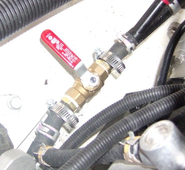
I put my valve between the jet intake and the wye fitting (where the flush line is connected), not between the wye and the engine as shown above. This way when I flush my engines, I close the valve which forces all the flush water through the engine and none leaks out the jet intake. I found for me the best place to put the valve was under the clean out tray, I did not want to reach to the rear of the engine compartment hanging all over a potentially hot engine to operate the valve. On the 2007-2009 models (not sure on other years) the cleanout tray has an access port next to the each cleanout plug. The cooling line for each motor runs directly below the access port. With the valve installed and the access cover removed, I can reach the valve.
Sorry I can't, I no longer own that boat.Can you take pictures and add to your post please.
Images appear to be broken @OperationROLSince our boats have an open vs. closed loop cooling system, there is a potential of flooding the engine through the exhaust if there is not a positive exhaust pressure pushing out and preventing water from entering there. While underway, and the engines are at high revs, there is no danger of that, but when an engine fails or you are being towed, the risk increases dramatically. Therefore, the owner's manual tells us to operate at no-wake mode to return to port. That way the water is not moving at a rapid rate and is less likely to jet up into the exhaust. However, operating at no-wake speed is painful if you are several miles from port and need to get back because of an inoperable engine. There are many that have shared their painful stories of operating for over 5 hours to get back to port. Since I am inpatient and would be poking my eyes out if I had to travel that far in no-wake mode, I decided to install a valve that would simply cut off the potential for water to enter the engines through the exhaust. Some others carry an automotive clamp or vice clamp with them to achieve the same thing. I worry about the damage the clamps may cause to the hose, so I opted for the valve and I like the clean look and convenience of just turning a valve.
This is actually a very simple and inexpensive mod. The hardest part is working in such a small area, especially if you have big hands like I do. Because of the little space I had to work in, it took me about and hour of work time to complete this project.
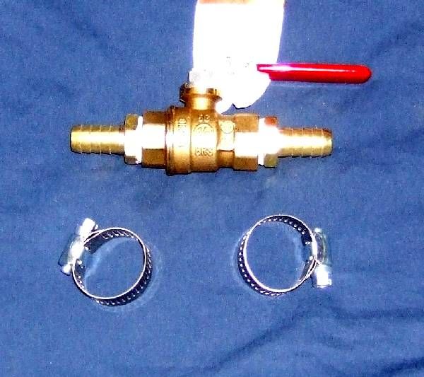
Supplies:
2 brass shutoff ball valves (1/2 inch or 5/8 would probably fit tighter)
4 barb fittings (same size as ball valve)
4 hose clamps
1 roll of plumbers tape
1 hose cutter (anything that can make the cut in the hose)
1 6" - 1' piece of 1/2 hose - It may have been 5/8 in so check hose size. (You may not need. This is incase you do not have enough hose exposed after cut to allow the barb fitting to fit all the way before hitting the fitting on the other end of the hose.

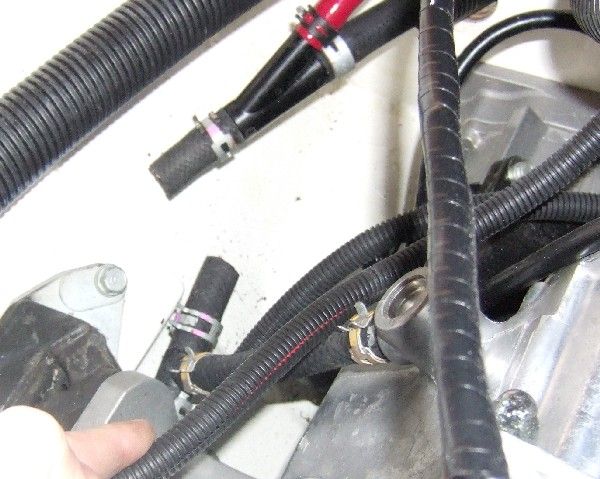
1. Locate the hose at the rear wall of the engine compartment at the bottom left of each engine.
2. Cut the hose before the "Y". It is about 4 inches long. If you cut exactly in the middle, you might be able to use the cut hose and not replace it with longer pieces when you are installing the barb fittings.

3. Wrap the threaded end of the barb fittings with plumbers tape.
4. Screw the threaded end of the barb fittings into each end of the valve and ensure a tight fit.
5. Make sure the clamps are in place but loose over the existing cut hose.
6. Insert the barb end of the fittings between the cut ends of the hose. You will know if you need to replace the cut hose if the barb end hits the fitting from the other side and does not fit in all the way. If that is the case, cut a piece of hose long enough to fit the barb fitting without hitting the fitting on the other side.
7. Slide the clamps into place and secure.


